Lap welding of steel articles having a corrosion resisting metallic coating

a technology of corrosion-resistant coating and lap welding, which is applied in the direction of welding/soldering/cutting articles, laser beam welding apparatus, manufacturing tools, etc., can solve the problems of zinc vapor bubbles at the faying surface, localized melting of materials in the assembly, and the application of lap welding processes to fabricate products from steel materials with pre-applied corrosion-resistant coatings, such as automobile bodies, can be problematic, and achieve the effect of reducing the risk o

Inactive Publication Date: 2008-02-14
ZHOU Y NORMAN
View PDF9 Cites 29 Cited by
  • Summary
  • Abstract
  • Description
  • Claims
  • Application Information

AI Technical Summary

Problems solved by technology

A concentrated heat source is then applied to one surface of the assembly, causing localized melting of materials in the assembly.
Application of lap welding processes to fabricating products from steel materials having preapplied corrosion-resistant coatings, such as automobile bodies, is problematic.
The zinc vapor can bubble out through the molten steel at the faying surface, possibly explosively.
This bubbling and explosive zinc vapor emission can disturb the small pool of liquid steel that is formed at the melted region and may eject the liquid steel from the desired joint region, thus weakening the weld.
In an exemplary welding application, the heat source is moved along a path, leaving an elongated weld seam, which will likely have periodic holes or other gross defects, if the steel b...

Method used


Image

  • Lap welding of steel articles having a corrosion resisting metallic coating
  • Lap welding of steel articles having a corrosion resisting metallic coating
  • Lap welding of steel articles having a corrosion resisting metallic coating

Examples


example 1

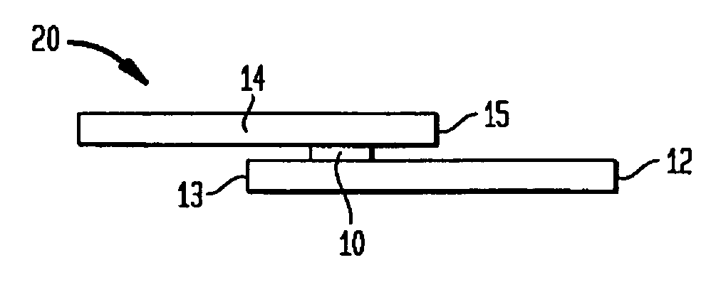
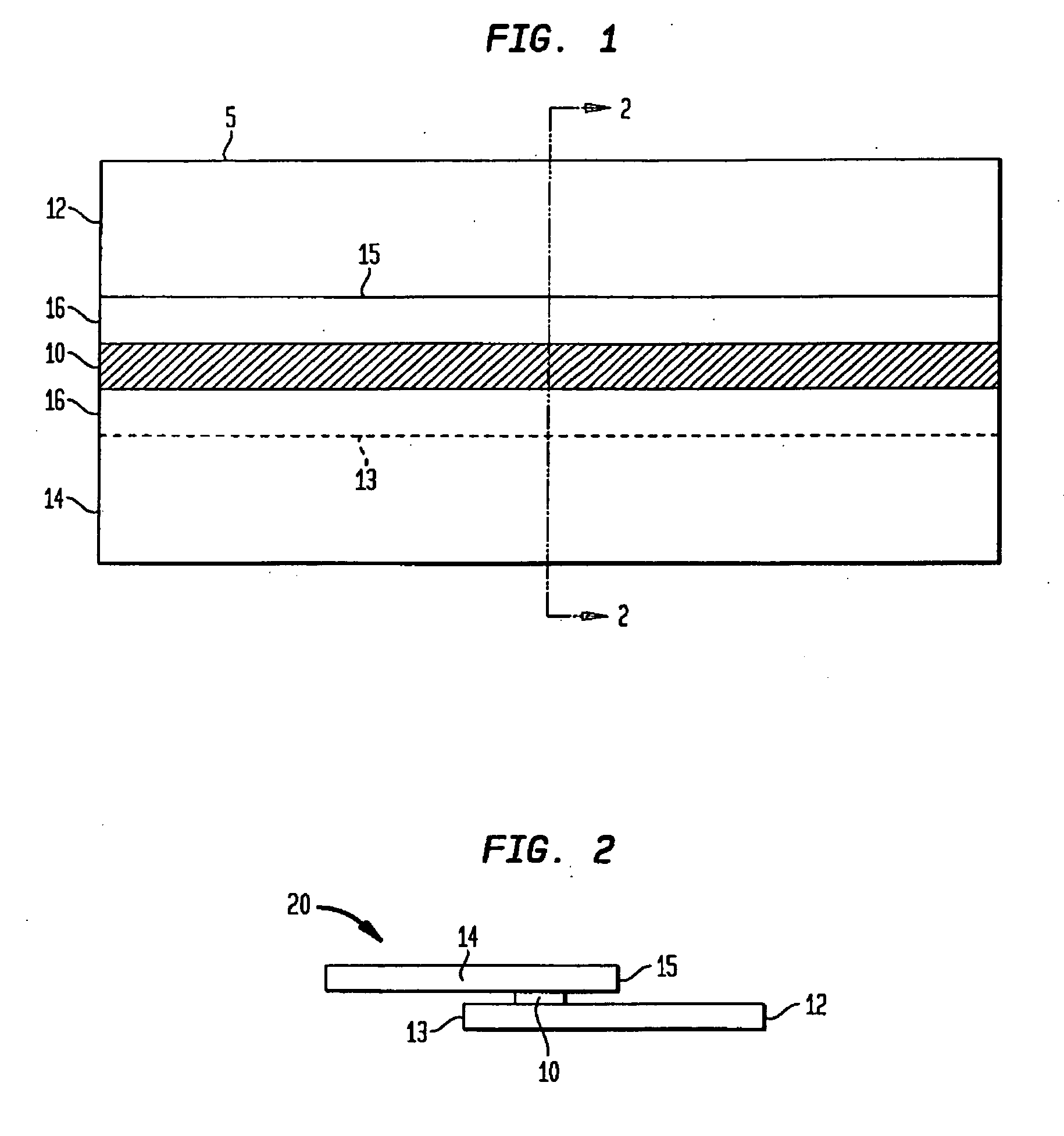
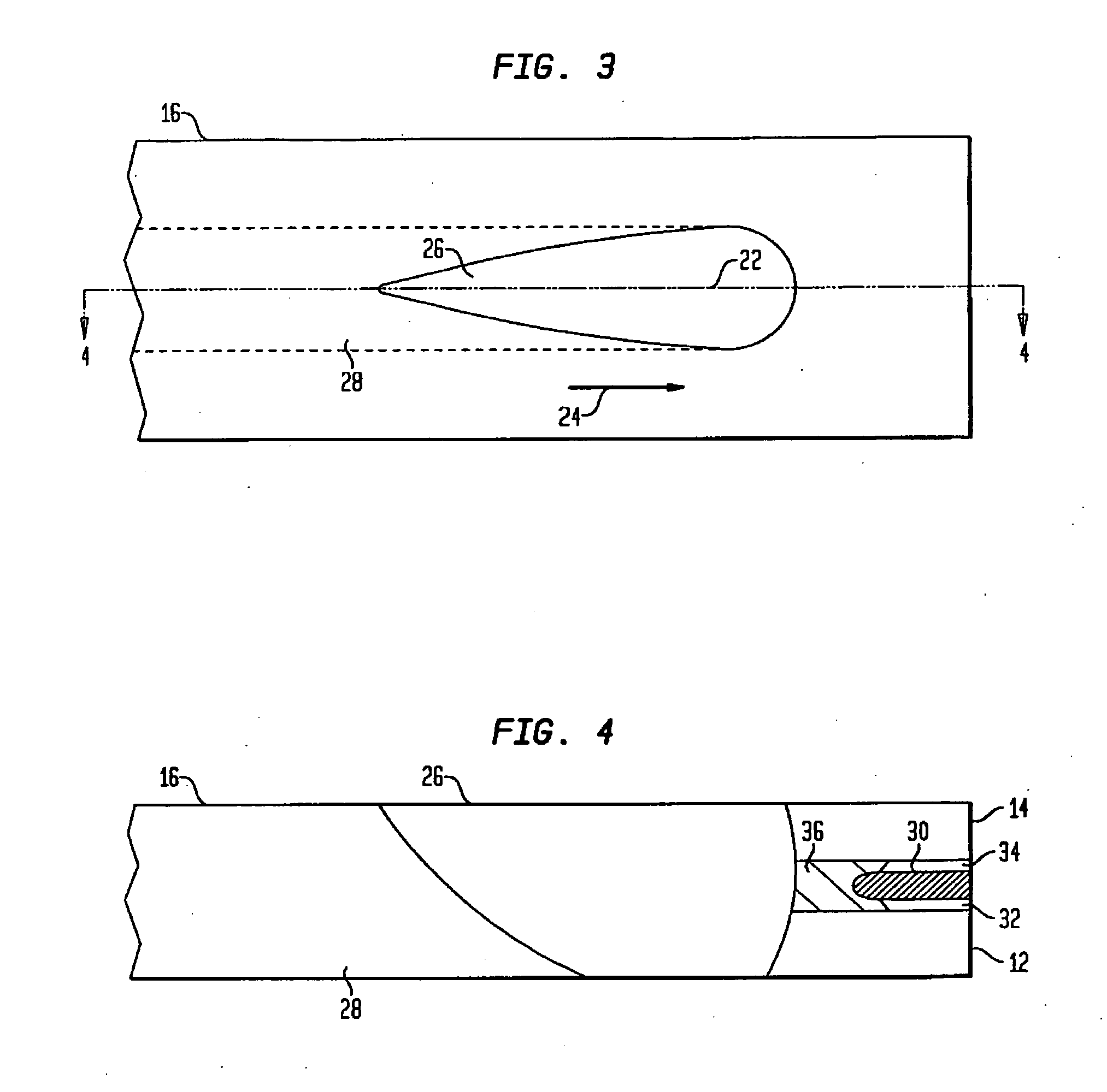
[0032]A series of experimental lap welds was made using a 4 kilowatt (kW) diode laser as the heat source. Two zinc coated steel sheets each having a thickness of 1 millimeter were tightly clamped together in a lap joint arrangement with a 0.025 mm thick aluminum foil inserted in the joint. Lap welds were consistently made without any weld pool surface disturbance or steel expulsion. Comparison experiments were performed in which a 0.025 mm thick copper foil was substituted for the aluminum foil, and welding was otherwise conducted under the conditions taught in U.S. Pat. No. 6,479,168. The resulting welds exhibited undesirable cracks.

example 2

[0033]Another series of experimental lap welds was made with the same laser and same grade of steel sheets as in Example 1, but with the sheets previously locally coated by cold spraying of particulate aluminum in the vicinity of the intended welds to an approximate thickness of 100 micrometers. Tightly clamped lap joints were consistently made without process disruption.

example 3

[0034]Further series of lap welds were made with the same steel specification and inserted aluminum foil as in Example 1, but with a 3 kW Nd:YAG laser as the moving heat source, producing similar improvement in welding process stability as found when using a diode laser.

[0035]While the present invention has been disclosed in a presently preferred context, it will be recognized that the present teachings may be adapted to a variety of contexts consistent with this disclosure and the claims that follow. For example, although the welding processes according to the present invention are desirably carried out by placing the steel sheets to be lap joined in a tightly clamped assembly, this tight assembly is not required. Other types of lasers, such as YAG and CO2 lasers, can be used. Heating sources other than lasers can potentially be used. Although the exemplary embodiments have employed steel sheets, such steel sheets do not have to be flat or straight, and the processes according to t...


PUM

PropertyMeasurementUnit
Percent by massaaaaaaaaaa
Weightaaaaaaaaaa

Abstract

Techniques are described for lap welding steel articles with a corrosion resistant coating. First and second steel members with a coating comprising zinc are welded together in a lap region. A metal selected to have a melting temperature below the boiling temperature of zinc, and to form a liquid alloy with the zinc, which alloy has a boiling temperature above the melting temperature of steel, is added to the lap region.

Description

FIELD OF THE INVENTION [0001]The present invention generally relates to the field of welding of steel articles, such as steel sheets, and more particularly to advantageous techniques for welding steel articles having a corrosion resistant metallic coating.BACKGROUND OF THE INVENTION [0002]Lap welding is a common method of assembling sheet metal structures. A lap weld is broadly defined as a weld between two overlapping materials such as sheets. Lap welding may be carried out, for example, by using a laser as a directed source of the concentrated heat energy needed to form a weld. In carrying out an exemplary laser welding process, two or more sheets of metal to be welded are clamped together, forming an assembly in a lap joint configuration. The metal surfaces that are tightly in contact, clamped for welding, are referred to as “faying surfaces.”[0003]A concentrated heat source is then applied to one surface of the assembly, causing localized melting of materials in the assembly. If...

Claims


Application Information

Patent Timeline
IPC IPC(8): B23K26/24
CPCB23K26/203B23K26/246B23K2203/04B23K26/3293B23K26/3206B23K26/32B23K26/211B23K26/244B23K2101/34B23K2103/04B23K2103/08B23K2103/50
Inventor LI, XIAOGANGLAWSON, W.H. SCOTTZHOU, Y. NORMAN
Owner ZHOU Y NORMAN
Why Eureka
Try Eureka