Method and apparatus for monitoring and control of suck back level in a photoresist dispense system

a technology of photoresist and dispense system, which is applied in the direction of liquid transfer device, liquid handling, instruments, etc., can solve the problems of insufficient volume of photoresist dispensed during coating operation, affecting the uniformity and thickness of coatings formed on the substrate, and generally affecting the film properties of photoresist, so as to achieve the effect of improving system stability

Active Publication Date: 2008-02-14
SCREEN SEMICON SOLUTIONS CO LTD
View PDF6 Cites 19 Cited by
  • Summary
  • Abstract
  • Description
  • Claims
  • Application Information

AI Technical Summary

Benefits of technology

[0013]Many benefits are achieved by way of the present invention over conventional techniques. For example, embodiments of the present invention provide methods and systems that provide improve monitoring (e.g., real time monitoring) of fluid levels in dispense systems. Moreover, embodiments described herein may be utilized to control dispense fluid levels in response to monitoring data. As a result, system stability is improved and early warning signals are detected, potentially preventing system failure. Depending upon the embodiment, one or more of these benefits, as well as other benefits, may be achieved. These and other benefits will be described in more detail throughout the present specification and more particularly below in conjunction with the following drawings.

Problems solved by technology

As an example, an inadequate volume of photoresist dispensed during a coating operation will generally impact the uniformity and thickness of coatings formed on the substrate.
Additionally, the dispense rate of the photoresist will generally impact film properties, including the lateral spreading of the resist in the plane of the substrate.
Conventional techniques for monitoring and controlling dispense operations for semiconductor process fluids are less than ideal.
However, these manual calibrations do not provide the level of versatility, automation, and speed desirable for current and future track lithography tools.
In addition, manual calibrations do not account for unexpected drift and errors during processing.

Method used


Image

  • Method and apparatus for monitoring and control of suck back level in a photoresist dispense system
  • Method and apparatus for monitoring and control of suck back level in a photoresist dispense system
  • Method and apparatus for monitoring and control of suck back level in a photoresist dispense system

Examples


Embodiment Construction

[0026]According to the present invention, techniques related to the field of semiconductor processing equipment are provided. More particularly, the present invention includes a method and apparatus for monitoring and control of fluids used to process semiconductors. Merely by way of example, the method and apparatus of the present invention have been applied to monitor and control fluids, for example photoresist, dispensed in a photolithography coating system. The method and apparatus can be applied to other processes for semiconductor substrates including chemical mechanical polishing.

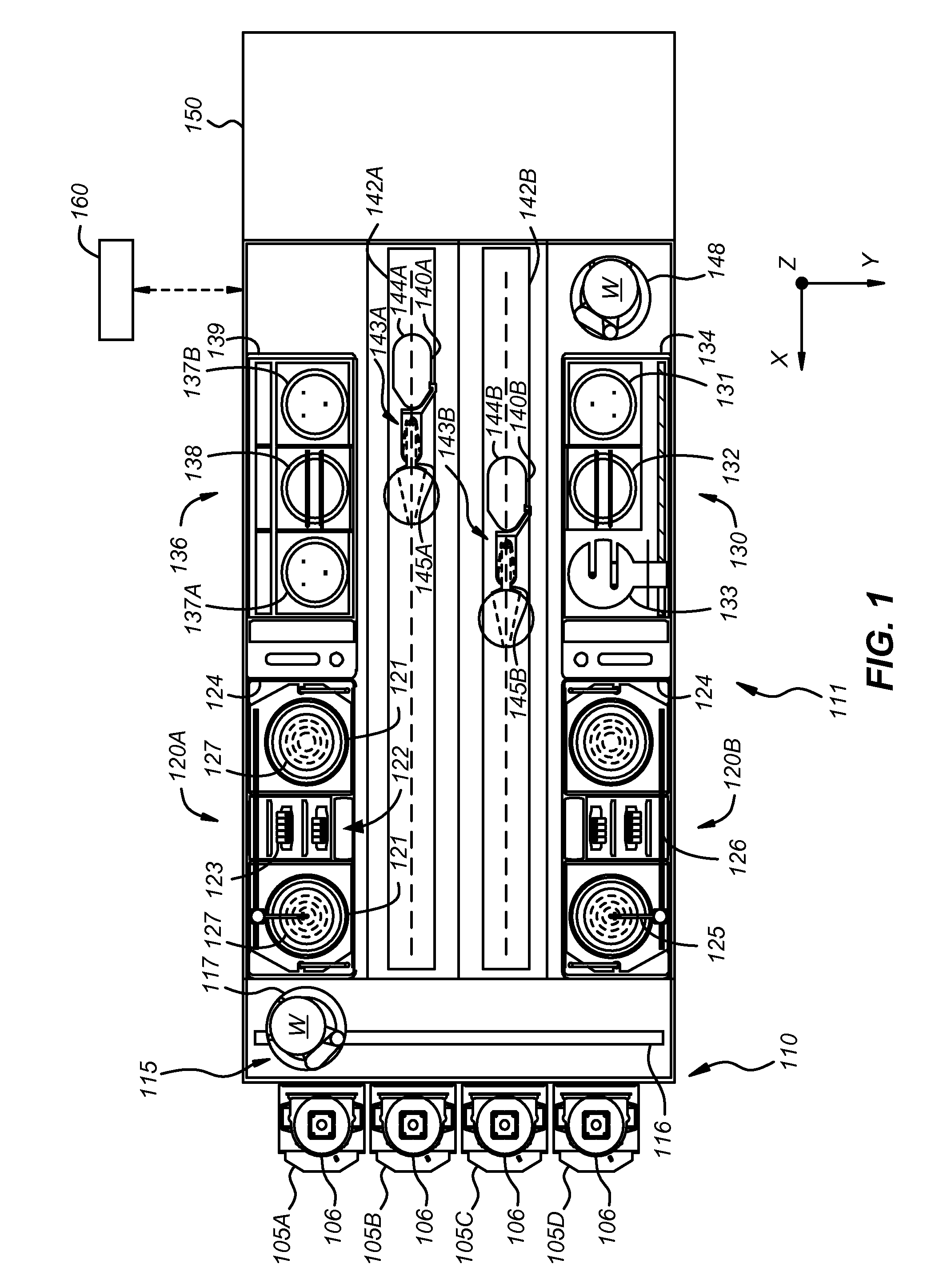
[0027]FIG. 1 is a plan view of an embodiment of a track lithography tool in which the embodiments of the present invention may be used. As illustrated in FIG. 1, the track lithography tool contains a front end module 110 (sometimes referred to as a factory interface) and a process module 111. In other embodiments, the track lithography tool includes a rear module (not shown), which is sometimes refer...


PUM


Abstract

An apparatus for monitoring a position of a semiconductor process fluid interface in a dispense nozzle includes an extended optical source adapted to provide an optical beam propagating along an optical path. The optical beam is characterized by a path width measured in a first direction aligned with a dispense direction. The apparatus also includes an optical detector coupled to the optical path and adapted to detect at least a portion of the optical beam and a dispense nozzle disposed along the optical path at a location between the extended optical source and the optical detector. The apparatus further includes a nozzle positioning member coupled to the dispense nozzle and adapted to translate the dispense nozzle in the first direction.

Description

CROSS-REFERENCES TO RELATED APPLICATIONS[0001]The present application claims the benefit under 35 U.S.C. § 119(e) of U.S. Provisional Patent Application No. 60 / 837,441, filed Aug. 11, 2006, entitled “Method and Apparatus for Monitoring and Control of Suck Back Level in a Photoresist Dispense System,” which is incorporated herein by reference in its entirety.BACKGROUND OF THE INVENTION[0002]The present invention relates generally to the field of substrate processing equipment. More particularly, the present invention relates to a method and apparatus for monitoring and control of fluids used to process semiconductors. Merely by way of example, the method and apparatus of the present invention are used to monitor and control fluids, for example photoresist, in a photolithography coating system. The method and apparatus can be applied to other processes for semiconductor substrates including chemical mechanical polishing.[0003]Modern integrated circuits contain millions of individual e...

Claims


Application Information

Patent Timeline
Patent Type & Authority Applications(United States)
IPC IPC(8): B67D5/08G01B11/14B67D7/08
CPCH01L21/67253H01L21/6715
Inventor PORRAS, ERICA R.RAMANAN, NATARAJAN
Owner SCREEN SEMICON SOLUTIONS CO LTD
Why Eureka
Try Eureka