Stent Graft Indwelling Device And Fixed Chip

a technology of indwelling device and stent, which is applied in the field of stent indwelling device and fixed chip, can solve the problems of difficult to overcome these problems, difficult to process metal molds for integral molding of dilators, and not always possible to insert sheaths, so as to improve safety and tracking properties, and safe place the released sten

Active Publication Date: 2008-02-14
KAWASUMI LABORITORIES INC +1
View PDF11 Cites 35 Cited by
  • Summary
  • Abstract
  • Description
  • Claims
  • Application Information

AI Technical Summary

Benefits of technology

[0007] However, unfortunately, these stent graft indwelling devices have a so-called one-piece structure in which the dilator is formed integrally with its head portion (called a swollen portion or fixed chip portion as well) of the dilator. Thereafter, the present inventors have found it desirable to ensure that the stent graft does not rotate in the sheath, that it does not move forward or backward and that it does not come off the dirator when it is housed in the sheath. Further, it has been found that when the stent graft is to be released from the sheath, it is desirable that the stent graft should come off easily and without any resistance. However, it is difficult to overcome these problems with the structure of the above-described dilator head.
[0008] Further, the dilator has the head portion whose swollen portion has a greatly expanded form like a spindle as compared with a holding portion (for example, see FIG. 2 of JP-A-2000-350785), so that it has been not easy to process a metal mold for integrally molding the dilator with an injection machine or the like. In actual medical care facilities, therefore, a craft man produces each dilator with swollen portion by piece by piece cutting work followed by thermal processing, etc., and the production thereof takes time. It has been also found that products vary in form.
[0009] The following problems have been also found. In the above stent graft indwelling device, the form of the above swollen portion of the dilator is fixed, so that it is not always possible that the sheath be inserted at a constant angle to th

Problems solved by technology

However, unfortunately, these stent graft indwelling devices have a so-called one-piece structure in which the dilator is formed integrally with its head portion (called a swollen portion or fixed chip portion as well) of the dilator.
However, it is difficult to overcome these problems with the structure of the above-described dilator head.
Further, the dilator has the head portion whose swollen portion has a greatly expanded form like a spindle as compared with a holding portion (for example, see FIG. 2 of JP-A-2000-350785), so that it has been not easy to process a metal mold for integrally molding the dilator with an injection machine or the like.
In the above stent graft indwelling device, the form of the above swollen portion of the di

Method used


Image

  • Stent Graft Indwelling Device And Fixed Chip
  • Stent Graft Indwelling Device And Fixed Chip
  • Stent Graft Indwelling Device And Fixed Chip

Examples


Embodiment Construction

[0041] This invention will be explained in detail below with reference to the drawings.

(Stent Graft Indwelling Device)

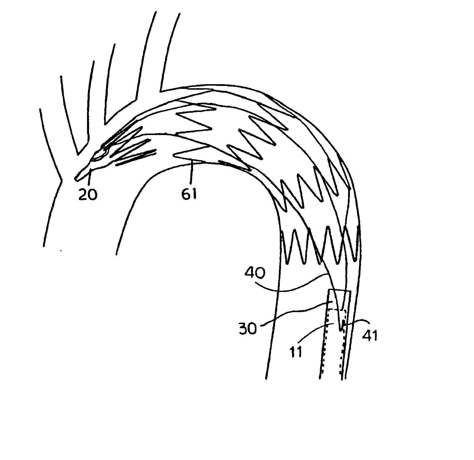
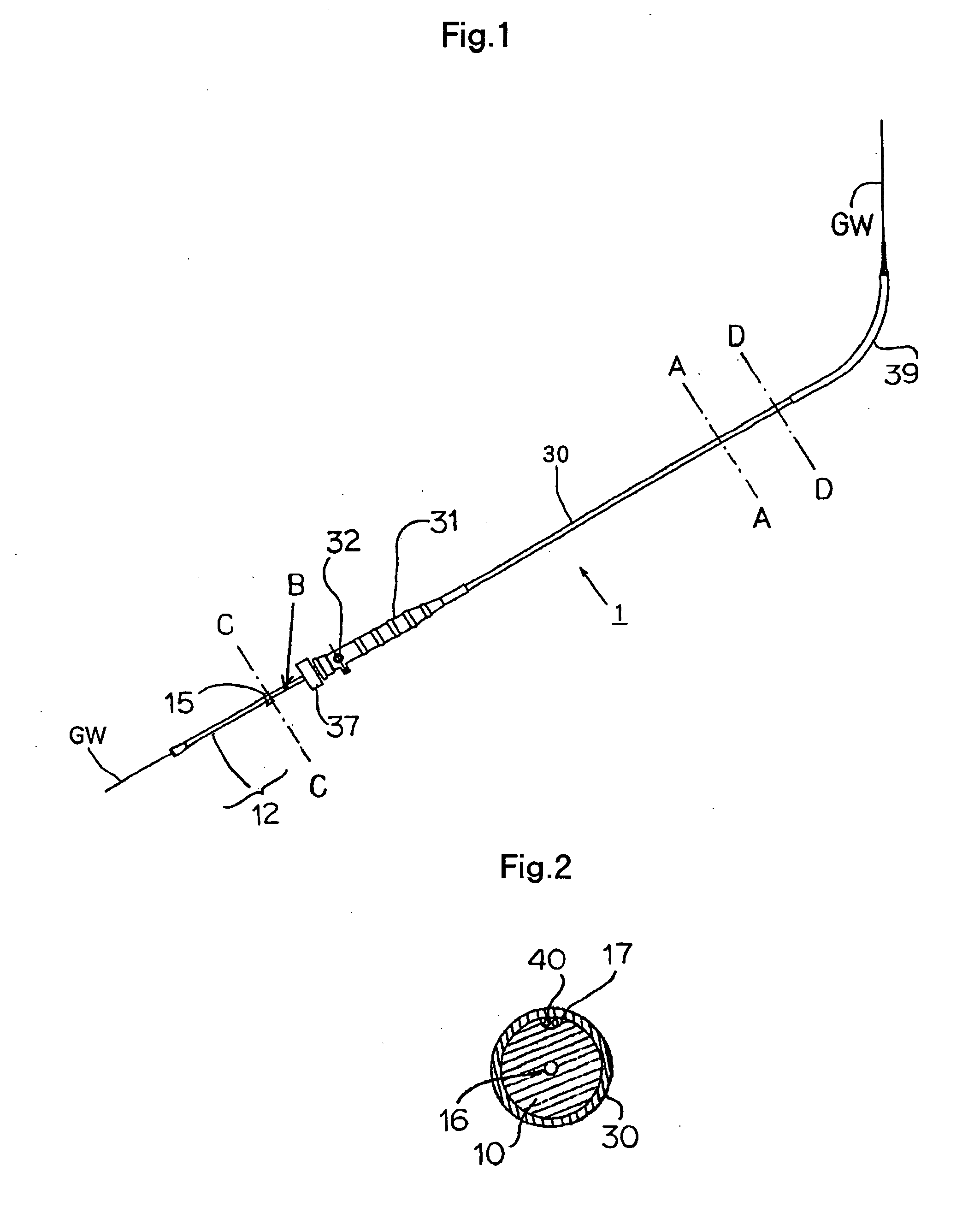
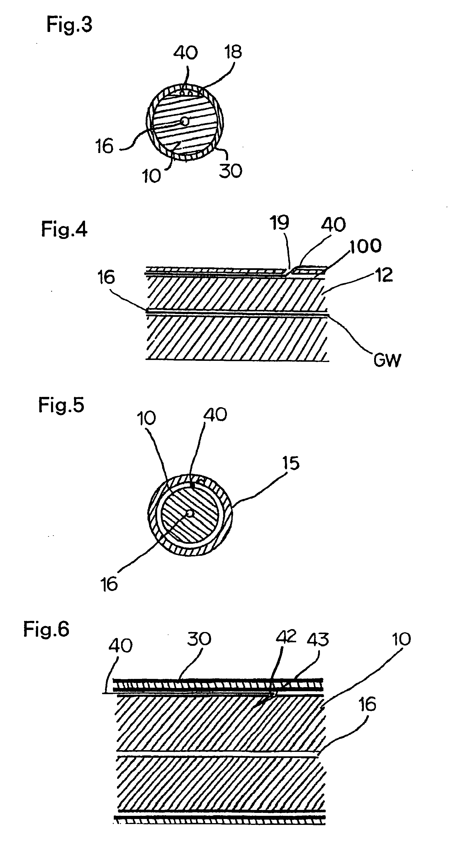
[0042] As shown in the exploded view of FIG. 9, the stent graft indwelling device 1 of this invention is an indwelling device comprising a dilator 10 having a stent graft holder 14 and a sheath 30 to be loaded with a stent graft 60 held on the stent graft holder 14 of the above dilator 10, and the stent graft indwelling device 1 is characterized in that the device have means for adjusting the insertion angle and / or indwelling site or place of the above stent graft 60 when the above stent graft 60 is released from the above sheath 30 and placed at the site.

[0043] And, the means for adjusting the insertion angle and / or indwelling site of the above stent graft 60 is realized preferably by a wire 40 and / or a fixed chip 20 mounted on the dilator 10.

[0044] As shown in FIG. 9, the feature of the indwelling device of this invention is that it is the stent graft indwelli...


PUM


Abstract

A stent graft indwelling device (1) comprising a dilator (10) and a sheath (30) in which the dilator (10) and a stent graft (60) are to be loaded, the stent graft indwelling device (1) having a wire (40) or a fixed chip (20) as means for adjusting the insertion angle and/or indwelling site of the stent graft (60) when the stent graft (60) is released from the sheath (30) in a diseased part by this indwelling device, so that the insertion angle and indwelling site can be finely adjusted in a blood vessel in a semi-expansion state where the stent graft is not completely expanded

Description

TECHNICAL FIELD [0001] This invention relates to a stent graft indwelling device that is designed for reliably indwelling a stent graft., for the treatment of an ecstatic disease (aneurysm), an arterial constrictive diseases or some other diseases at a safe site of a diseased part and that decreases the pains and burdens of a patient and reduces the cost or expenses, and relates also to improvements in a fixed chip to be loaded on a dilator of the stent graft indwelling device. BACKGROUND ART [0002] The present inventors have proposed, by JP-A-2000-262632, a stent graft indwelling device having a catheter, a pushing rod (also called “dilator”) and a sheath, in which a swollen portion that has the form, for example, of an ellipsoid, for blocking or sealing a leading end of the sheath is provided in the vicinity of the leading end of the catheter and the swollen portion is provided-with an engagement means such as a notch or the like so that a hook attached to the leading end of a ste...

Claims


Application Information

Patent Timeline
IPC IPC(8): A61F2/06A61F2/00A61F2/966A61M29/00
CPCA61F2/07A61F2/95A61F2002/9511A61F2002/9583A61F2220/0075A61F2/89A61F2002/075A61F2220/0058A61F2250/0097
Inventor ISHIMARU, SHINYOKOI, YOSHIHIKO
Owner KAWASUMI LABORITORIES INC
Why Eureka
Try Eureka