Methods and apparatus for mitral valve repair

a technology of mitral valve and valve body, applied in the field of methods and apparatus for valve repair, can solve problems such as heart failure, left ventricular enlargement, heart valve malfunction, etc., and achieve the effect of inhibiting or preventing leaflet prolaps

Inactive Publication Date: 2008-02-14
BUCH WALLY +1
View PDF35 Cites 268 Cited by
  • Summary
  • Abstract
  • Description
  • Claims
  • Application Information

AI Technical Summary

Benefits of technology

[0021] In use, because the chordae tendineae may loosely pass through the central opening, the ring may freely slide in vivo along the chordae tendineae while retained by the atraumatic ends. During systole, because of the tissue contraction and forced blood flow, the ring may be urged to slide along the chordae tendineae into a superior position where presentation surface is urged or pressed against the posterior mitral leaflet. As the presentation surface is pressed against the mitral valve, the posterior mitral leaflet may be supported by the ring in inhibiting or preventing prolapse of the leaflet.

Problems solved by technology

Clinical cardiac decomposition (or heart failure) results from heart valve malfunction, such as mitral insufficiency.
This allows blood to backflow into the left atrium resulting in left ventricular overload and if the condition is not corrected, the added workload will eventually cause left ventricular enlargement and dysfunction resulting in heart failure.
Rings of various designs used to perform annuloplasty can have an adverse effect on mitral valve function.
The clinical acceptance of posterior leaflet immobilization after mitral valve annuloplasty is felt to negatively impact the distribution of closing stress on the leaflets.
The potential downside is increased collagen deposition resulting in leaflet thickening which can further stress leaflet closure.

Method used


Image

  • Methods and apparatus for mitral valve repair
  • Methods and apparatus for mitral valve repair
  • Methods and apparatus for mitral valve repair

Examples


Embodiment Construction

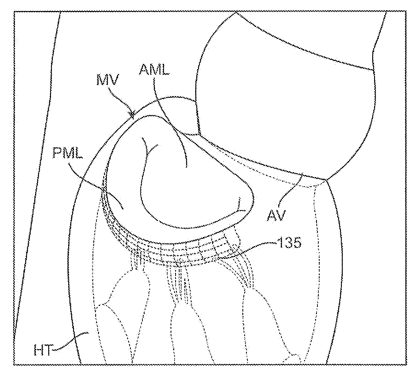
[0069] By supporting a portion of the mitral valve, particularly the posterior leaflet, in a frozen or immobile position while avoiding reduction of the mitral annulus, a buttress may be created against which the anterior leaflet may close. By maintaining the posterior mitral leaflet frozen or immobile in its closed position, this may alleviate stress imparted upon both leaflets and enable both posterior and anterior leaflets to properly coapt in use, particularly for alleviating conditions such as mitral valve regurgitation. Generally, an implantable device may be advanced and positioned intravascularly beneath the posterior leaflet of the mitral valve utilizing any number of percutaneous techniques.

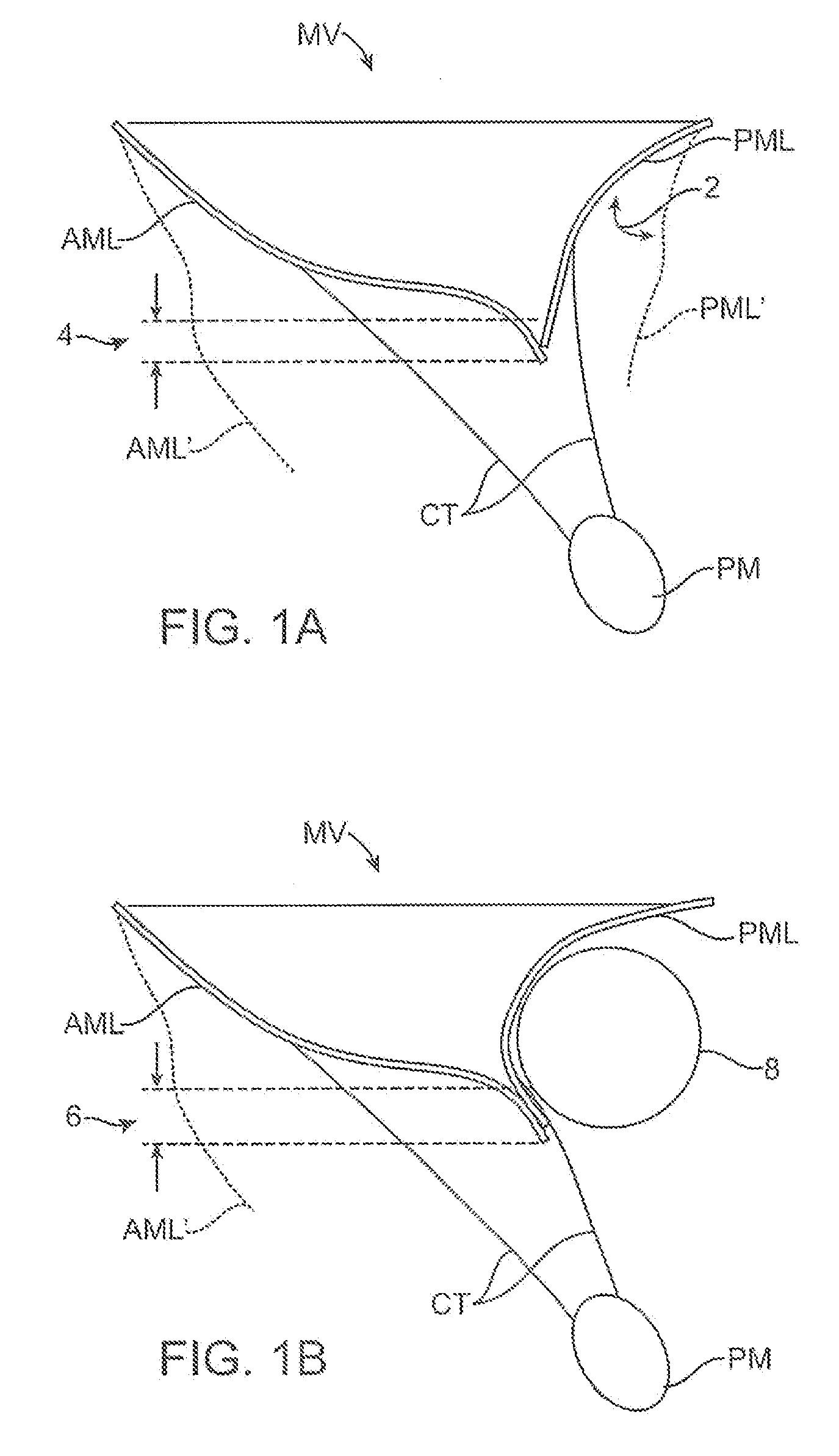
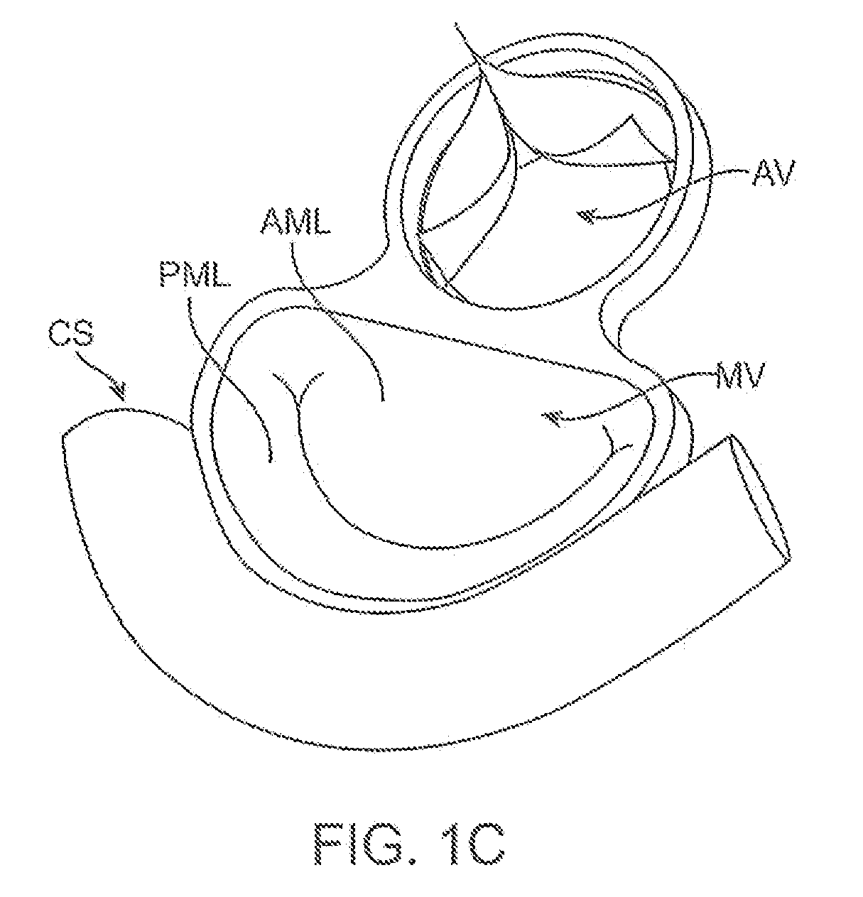
[0070] A representative side view of the anterior mitral leaflet AML and posterior mitral leaflet PML of a mitral valve MV are illustrated in FIG. 1A. When the heart is in systole, the leaflets are typically opposed relative to one another over a coaptation length 4, as shown. During d...


PUM


Abstract

Methods and apparatus for mitral valve repair are disclosed herein where the posterior mitral leaflet is supported or buttressed in a frozen or immobile position to facilitate the proper coaptation of the leaflets. An implantable apparatus may be advanced and positioned intravascularly beneath the posterior leaflet of the mitral valve. The apparatus may include one or more individual balloon members, each of which may be optionally configured with supporting integrated structures. A magnet chain catheter may be positioned within the coronary sinus and adjacent to the mitral valve to magnetically secure the apparatus in position beneath the posterior mitral leaflet. Alternatively, a split-ring device may be placed about the chordae tendineae supporting the mitral valve such that the ring slides along the chordae tendineae alternately against the mitral leaflet and towards the papillary muscles during systole and diastole.

Description

CROSS-REFERENCE TO RELATED APPLICATIONS [0001] The application claims the benefit of priority to U.S. Prov. Pat. App. 60 / 822,360 filed Aug. 14, 2006, which is incorporated herein by reference in its entirety.FIELD OF THE INVENTION [0002] The invention relates to methods and apparatus for valve repair in a patient body. More particularly, the invention relates to methods and apparatus for mitral valve repair for correcting conditions such as mitral valve regurgitation. BACKGROUND OF THE INVENTION [0003] Essential to normal heart function are four heart valves, which allow blood to pass through the four chambers of the heart in a specified direction. These valves have either two or three cusps or leaflets, which are comprised of fibrous tissue that are attached to the walls of the heart. The cusps open when the blood is flowing correctly and then close to form a tight seal to prevent backflow. [0004] The four chambers are known as the right and left atria (upper chambers) and right an...

Claims


Application Information

Patent Timeline
Patent Type & Authority Applications(United States)
IPC IPC(8): A61F2/24
CPCA61F2/2445A61F2/2451A61F2/2454A61F2/2466
Inventor BUCH, WALLYREALYVASQUEZ, FIDEL
Owner BUCH WALLY
Why Eureka
Try Eureka