
System and method for performing processing in a testing system

a testing system and processing technology, applied in the field of test systems, can solve the problems of non-deterministic test, high total cost of ate systems, and inability to adapt to mass production, so as to improve the hardware associated with a tester more easily, the application is more easily created, and the effect of improving the hardwar

Active Publication Date: 2008-02-14
JONATHAN R GOLDSMITH CHAPTER 7 TRUSTEE OF THE BANKRUPTCY ESTATE OF ASTERION +1
View PDF29 Cites 13 Cited by
  • Summary
  • Abstract
  • Description
  • Claims
  • Application Information

AI Technical Summary

Benefits of technology

This approach reduces the overall cost of ATE systems, enhances flexibility, and speeds up the development and maintenance of test equipment, allowing for faster adaptation to new devices and functionality, thereby addressing the inflexibility and high costs associated with conventional ATE systems.

Problems solved by technology

Because they are highly specialized, they do not lend themselves to be mass-produced, or include mass-produced hardware and software components.
Further, according to one aspect of the present invention, it is appreciated that the total cost of ATE systems are expensive due primarily to the tight coupling between software and hardware.
In a deterministic system such as an ATE system, such a change may cause a test program to perform differently, producing non-deterministic test results.
Practically, in a production test environment, this results in user (e.g., test engineers) being reluctant to implement new features in existing production test systems.
For instance, if a new software-based test function is made available in an existing test system, introduction of that new software may break the operation of the current software.
For instance, if a software driver is replaced by a later-version driver, the test system may not function in the same way, and test results may be affected.
Similarly, if an improved hardware (e.g., a test instrument) is added to an existing ATE system, the hardware and / or software of the existing system may not function in the same way or at all.
This results in inefficient use of testing resources, and limited reuse of testing platforms.
Further, the test hardware and software producer must rigorously test all possible permutations of components to prohibit problems from occurring in the field, thus increasing production costs and the overall cost of the test equipment.
Because their programs use the tightly-coupled hardware and software, their programs are also highly dependent on this tightly-coupled system, and any changes in the underlying system may cause their test programs to operate differently than expected.
Because of this, test engineers are generally unwilling to consider new software and / or hardware changes to existing production test environments.
Such test equipment may be used, for example, in manufacturing of electronic devices, and a failure of such equipment may impact manufacturing schedules.

Method used


Image

  • System and method for performing processing in a testing system
  • System and method for performing processing in a testing system
  • System and method for performing processing in a testing system

Examples


programming example

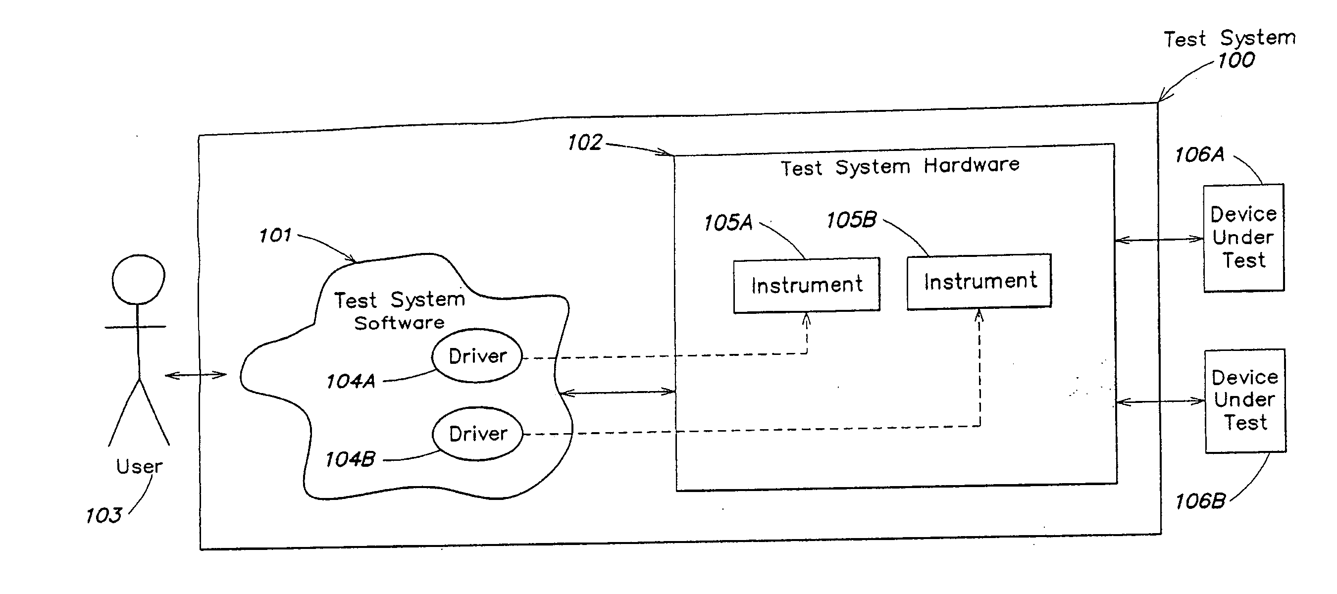
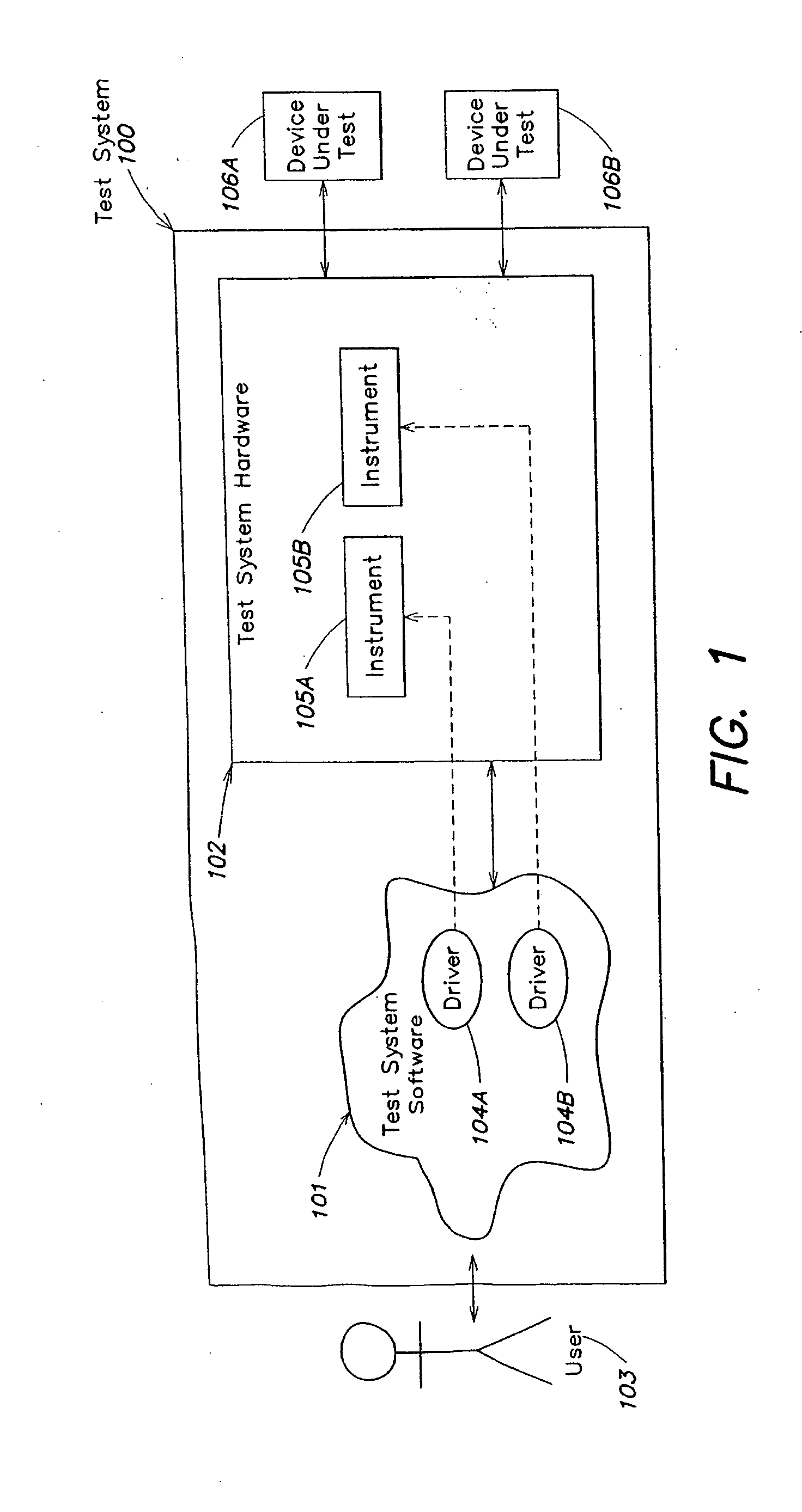
[0149] Instrument independence is an important feature of a test system architecture, according to one embodiment of the present invention. This feature allows independent improvements or modifications of each instrument without the need for coordinated simultaneous upgrades. In order to maintain this independence, the test system provides a system driver function via the system PI to manage the synchronization and triggering subsystem. In this scheme, the system PI acts as a mediator between instruments. The system PI manages the use and availability of signal lines, sets trigger connections and modes, and keeps delay information and does other housekeeping functions.

[0150] Starting with the user program or application (e.g., 901), the user program calls functions of the virtual multisite instruments (VMIs) which in turn call functions of the instrument physical drivers (or PIs). When PIs are created, they are provided access to the system PI for system level functions, calibratio...


PUM


Abstract

A system and method is provided for performing processing in a test system. A flexible platform may be provided for developing test programs for performing automated testing. In one such platform, the tester and its instruments are isolated from the tester operating system, permitting any tester operating system to be used. In another example implementation, a user layer of the platform is isolated from the physical layer of the architecture, permitting hardware-independent test programs that can be created and used among different testers having different test hardware and software. In yet another implementation, execution of a test program is isolated from a tester platform operating system, permitting the test program to function independent from the tester platform. In another embodiment, functionality is implemented on the platform such that functions are only added, and that existing links to functions are not broken, ensuring continued test system operation when new software, hardware and / or features are added to the platform. The test system may include a non-deterministic computer system. In one example test system, the system forces execution of one or more computer instructions performed by the non-deterministic computer system to execute within a constant execution time. A deterministic engine, if necessary, waits a variable amount of time to ensure that the execution of the computer instructions is performed over the constant execution time. Because the execution time is constant, the execution is deterministic and therefore may be used in applications requiring deterministic behavior. For example, such a deterministic engine may be used in automated test equipment (ATE) applications.

Description

REFERENCE TO RELATED APPLICATIONS [0001] This application claims priority under 35 U.S.C. §119(e) to U.S. Provisional Application Ser. No. 60 / 819,610, entitled “SYSTEM AND METHOD FOR PERFORMING PROCESSING IN A TESTING SYSTEM,” filed Jul. 10, 2006, and to U.S. Provisional Application Ser. No. 60 / 819,762, entitled “SYSTEM AND METHOD FOR PROCESSING IN A TEST SYSTEM,” filed Jul. 10, 2006, each of which applications are incorporated by reference in their entirety.BACKGROUND OF THE INVENTION [0002] 1. Field of the Invention [0003] The invention relates generally to test systems, and more specifically, to test systems in the automatic test equipment (ATE) area. [0004] 2. Discussion of the Related Art [0005] Today, most test equipment in the ATE area involves one or more computer systems. A computer system that implements testing steps must be reliable and must generate test steps in a deterministic way. That is, the computer systems must be capable of producing consistent results. One prob...

Claims


Application Information

Patent Timeline
Patent Type & Authority Applications(United States)
IPC IPC(8): G06F9/44G01M99/00
CPCG01R31/3183G01R31/2834G06F9/06G01R31/3181
Inventor BLANCHA, BARRY E.LECHOWICZ, LESZEK JANUSZHELM, STEPHEN S.ADAM, SEAN PATRICKCAMARGO, JORGEHEIL, CARLOSMENDES, PAULO
Owner JONATHAN R GOLDSMITH CHAPTER 7 TRUSTEE OF THE BANKRUPTCY ESTATE OF ASTERION
Learn More