Packaging laminate, method of producing a packaging container and the packaging container

a technology of packaging container and packaging laminate, which is applied in the field of packaging laminate, can solve the problems of disturbed movement of the anvil jaw, poor mechanical settings of the sealing machine, and poor guiding of the tube, so as to reduce the sensibility reduce the melting enthalpy, and reduce the effect of the ultrasonic vibration heat sealing system

Inactive Publication Date: 2008-02-21
TETRA LAVAL HLDG & FINANCE SA
View PDF20 Cites 1 Cited by
  • Summary
  • Abstract
  • Description
  • Claims
  • Application Information

AI Technical Summary

Benefits of technology

[0013] Of course, the prime object of the invention is to provide strong and liquid-tight transversal seals in packaging containers produced from the packaging laminate according to the invention, also at the overlaps between the transversal seals and the longitudinal seal in the packaging container.
[0019] The sealing window concept is well known by the skilled man and is defined as the energy range within which sealing is possible. A low lowermost limit means that an acceptable seal takes place at low energy levels, which in turn decreases the sensibility of the ultrasonic vibration heat sealing system to the mechanical settings and to other prevailing circumstances. Even if a low pressure is applied in some spots along the sealing area, the energy converted into heat will be enough to melt the heat sealable thermoplastic sealing ply having a low melt enthalpy, thus allowing a strong and liquid-tight seal to be formed. A high uppermost limit of the sealing window means that a considerable energy supply can be allowed.
[0020] Moreover, it is preferred that the inside layer also comprises a ply consisting of so called C4, C6 or C8 linear low density polyethylene (C4 LLDPE, C6 LLDPE, C8 LLDPE). C4, C6 and C8 LLDPE are polyethylenes which are obtained by small quantities of C4, C6 or C8 alpha olefins being used as comonomers during the polymerisation of ethylene. Preferably, this C4, C6 or C8 LLDPE ply, and even more preferred a C6 or LLDPE ply, is the second ply as counted from the outer surface of the laminate, i.e. the ply which is in direct contact with the heat sealable thermoplastic material ply having a low melt enthalpy. The combination of these two plies will beneficially and surprisingly result in extremely strong and liquid-tight transversal seals being achieved despite deviations in the mechanical settings of the sealing machine.
[0021] It has moreover surprisingly been found that the openability of an opening device consisting of a perforation partly passing through the transversal seal is very good, despite the fact that the transversal seal is so strong.
[0022] A laminate according to the invention is especially well adapted to be used in connection with ultrasonic vibration heat sealing. A feature of the ultrasonic vibration heat sealing technique is that the entire material under pressure between the ultrasonic horn and the anvil jaw is heated up by the vibrations at the same time. For a strong seal to take place, it is enough that the outermost layer (i.e. the outermost layer on the side of the laminate that is facing the inside of the container) reaches the melting point. As a consequence it is enough to provide only a thin sealing ply of the heat sealable thermoplastic material with low melt enthalpy in the inside layer, in order to decrease the sensibility of the ultrasonic vibration heat sealing process and to achieve strong and liquid-tight transversal seals. In other words, even a thin layer of the heat sealable thermoplastic according to the invention is enough to beneficially lower the lowermost limit of the sealing window.

Problems solved by technology

Especially, the object is to provide a packaging laminate which is more forgiving to prevailing circumstances such as poor tolerances in the mechanical settings of the sealing machine, poor tube guiding, disturbed movements of the anvil jaws, poor parallelism between the ultrasonic horns and the cutting rails, presence of foreign matter in the area of the seals, etc.

Method used


Image

  • Packaging laminate, method of producing a packaging container and the packaging container
  • Packaging laminate, method of producing a packaging container and the packaging container
  • Packaging laminate, method of producing a packaging container and the packaging container

Examples


examples

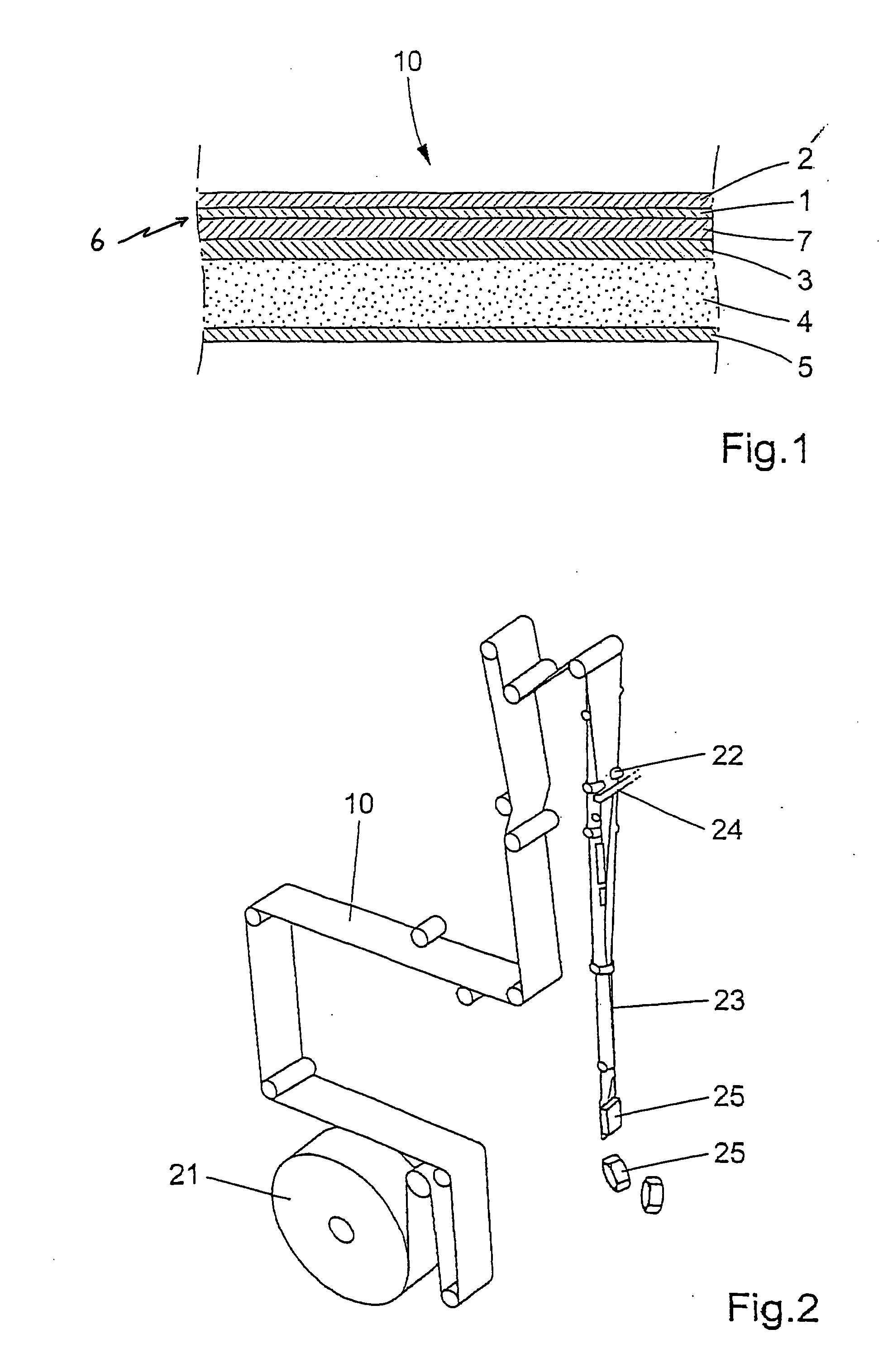
[0044] In the examples three different laminates according to the invention were tested and also one reference laminate of conventional type. The laminates are specified in table 1. L1 and L2 had been produced by laminating a film together with the paperboard / decor layer. The film of L1 consisted of a first, second and fourth ply according to the above description. The film of L2 consisted of a second and fourth ply. The reference and the L3 laminate had been produced by extrusion coating. In table 1, the numbering of the plies follows the numbering shown in FIG. 1. As is evident from table 1, an inside layer in a laminate according to the invention may comprise different numbers of plies, meaning that the first ply 1, the fourth ply 7 or the third ply 3 may be the ply which is arranged in direct contact with the second sealing ply 2.

TABLE 1ReferenceL1L2L3Sealing ply 2LDPE,Dow ExxonJPC Kernel,27 g / m2AffinityExceed32 g / m2PL1880,ML1023,5.4 g / m211 g / m2Melt enthalpy,120.8 J / g90 J / g110...


PUM

PropertyMeasurementUnit
timeaaaaaaaaaa
timeaaaaaaaaaa
melt enthalpyaaaaaaaaaa

Abstract

Method in connection with the production of a packaging container, including a) choosing or manufacturing a web shaped packaging laminate according to claim 1, b) converting said packaging laminate to a continuous tube by overlapping two longitudinal edges of the web shaped packaging laminate and heat sealing the overlapped edges to provide a longitudinal seal, c) filling the tube with contents, d) intermittently performing transversal seals by mechanically pressing together two transversal anvil jaws while the filled tube is arranged there between, e) while at the same time providing energy to the packaging laminate at an area of said transversal seal.

Description

CROSS-REFERENCE TO RELATED APPLICATIONS [0001] This application is a divisional of U.S. application Ser. No. 10 / 471,565, filed Mar. 22, 2004, the contents of which are incorporated herein by reference, which was the National Stage filing under §371 of International Application No. PCT / SE02 / 00436 filed Mar. 11, 2002, which in turn claims priority to Swedish Application No. 0100858-0, filed Mar. 12, 2001.TECHNICAL FIELD [0002] This invention relates to a packaging laminate for a packaging container, preferably for liquid food contents, which packaging laminate comprises a structural base layer, and an inside layer. The invention also relates to a method of producing a packaging container from the packaging laminate, and to the packaging container built up from the packaging laminate. PRIOR ART AND PROBLEMS [0003] Food packaging processes of today (with the term “food” is meant all sorts of solid and liquid food, such as juices, milk and other beverages as well as pastes, soups, jellie...

Claims


Application Information

Patent Timeline
Patent Type & Authority Applications(United States)
IPC IPC(8): B65B43/08B65B9/10B29C53/40B29C65/00B29C65/08B29C65/50B32B7/02B32B27/00B32B27/32B65B51/22B65D65/40B65D75/48
CPCB29C53/40Y10T428/1352B29C65/5042B29C66/346B29C66/723B29C66/73115B29C66/80B29C66/849B29C66/929B29C66/949B32B27/32B65D75/48B29C65/08B29C66/81435B29C65/5021B29C65/4815B29C66/9241B29C66/81431B29C65/00B29C66/1122B29C66/4312B29C66/4322B29C66/45B29C66/49B29C66/71B29C66/72321B29C66/72328B29C66/72341B29C66/81427B29C66/8322B29C66/836B29L2031/7166B29K2023/0633B29K2023/0625B29K2023/06
Inventor CAPASSO, SALVATORECHIQUET, ANDRE
Owner TETRA LAVAL HLDG & FINANCE SA
Why Eureka
Try Eureka