Gear bearing drive

a technology of bearings and gears, applied in the direction of gearing, hoisting equipment, prosthesis, etc., can solve the problems of insufficient motion of higher-level amputees in order to properly activate prosthesis, and difficult to achieve satisfactory grip strength, etc., to achieve high absolute or incremental position precision, save weight and space, and compact size

Inactive Publication Date: 2008-02-21
NORTHEASTERN UNIV +1
View PDF17 Cites 63 Cited by
  • Summary
  • Abstract
  • Description
  • Claims
  • Application Information

AI Technical Summary

Benefits of technology

[0009] A gear bearing drive according to the present invention is a compact mechanism with the ability to operate as an actuator providing torque and as a joint providing support. This is possible because of the combination of external rotor brushless DC motor technology and gear bearing technology. It can replace traditional motor gear train assemblies with a single mechanism saving weight and space. Additionally, high absolute or incremental positional precision is inherent to the design with the addition of an encoder to the drive motor. Its compact size, high precision and joint capabilities allow it to have applications in the aerospace, space, manufacturing, transportation and other industries.

Problems solved by technology

While these prostheses are generally lightweight and low-cost, they do have significant disadvantages.
Higher level amputees are often unable to generate sufficient motion in order to properly activate the prosthesis.
Achieving satisfactory grip strength is also difficult due to the mechanical limitations of currently available terminal devices and grasp patterns.
While offering improved performance over many body powered components, these devices are still inadequate for many tasks.

Method used


Image

  • Gear bearing drive
  • Gear bearing drive
  • Gear bearing drive

Examples


Embodiment Construction

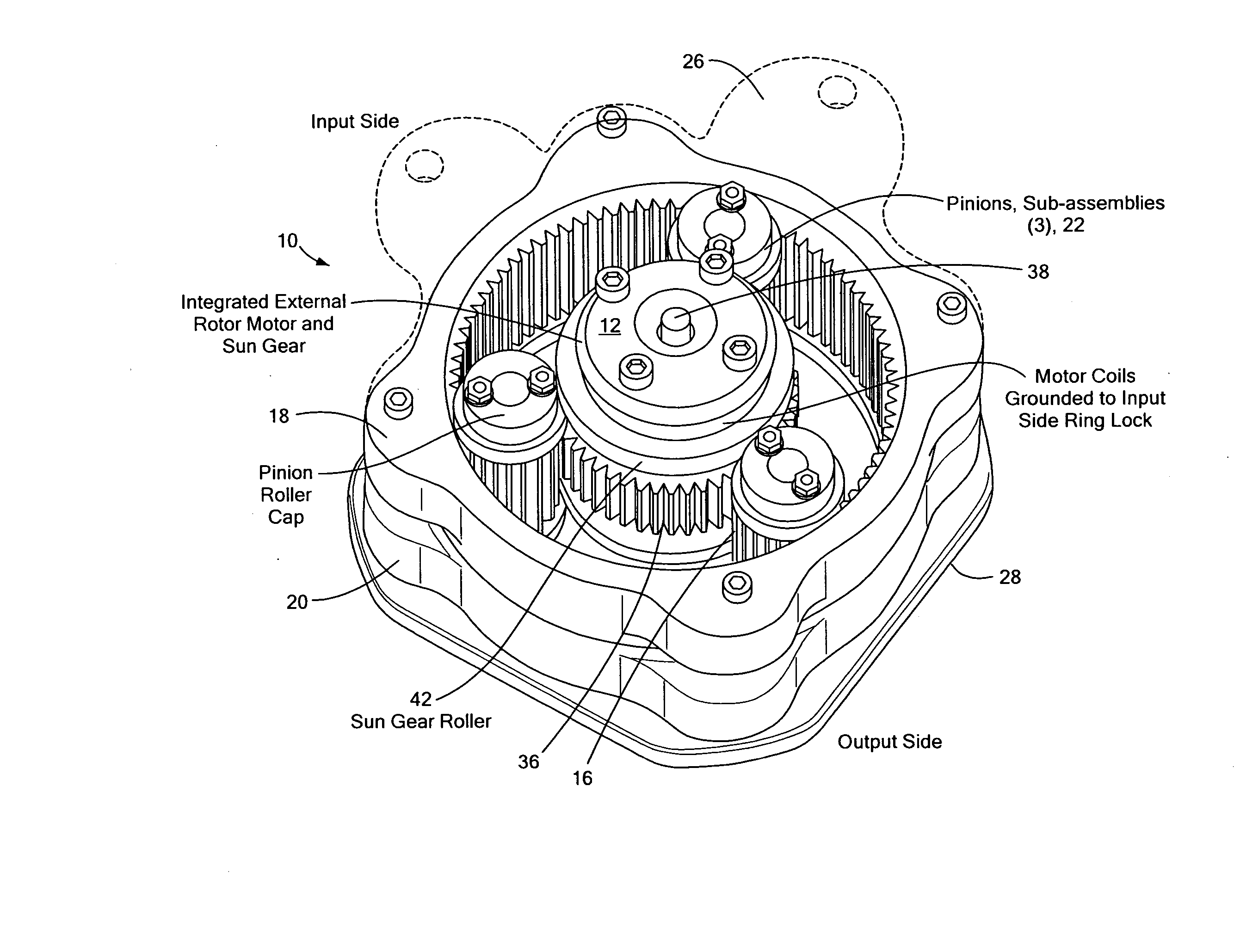
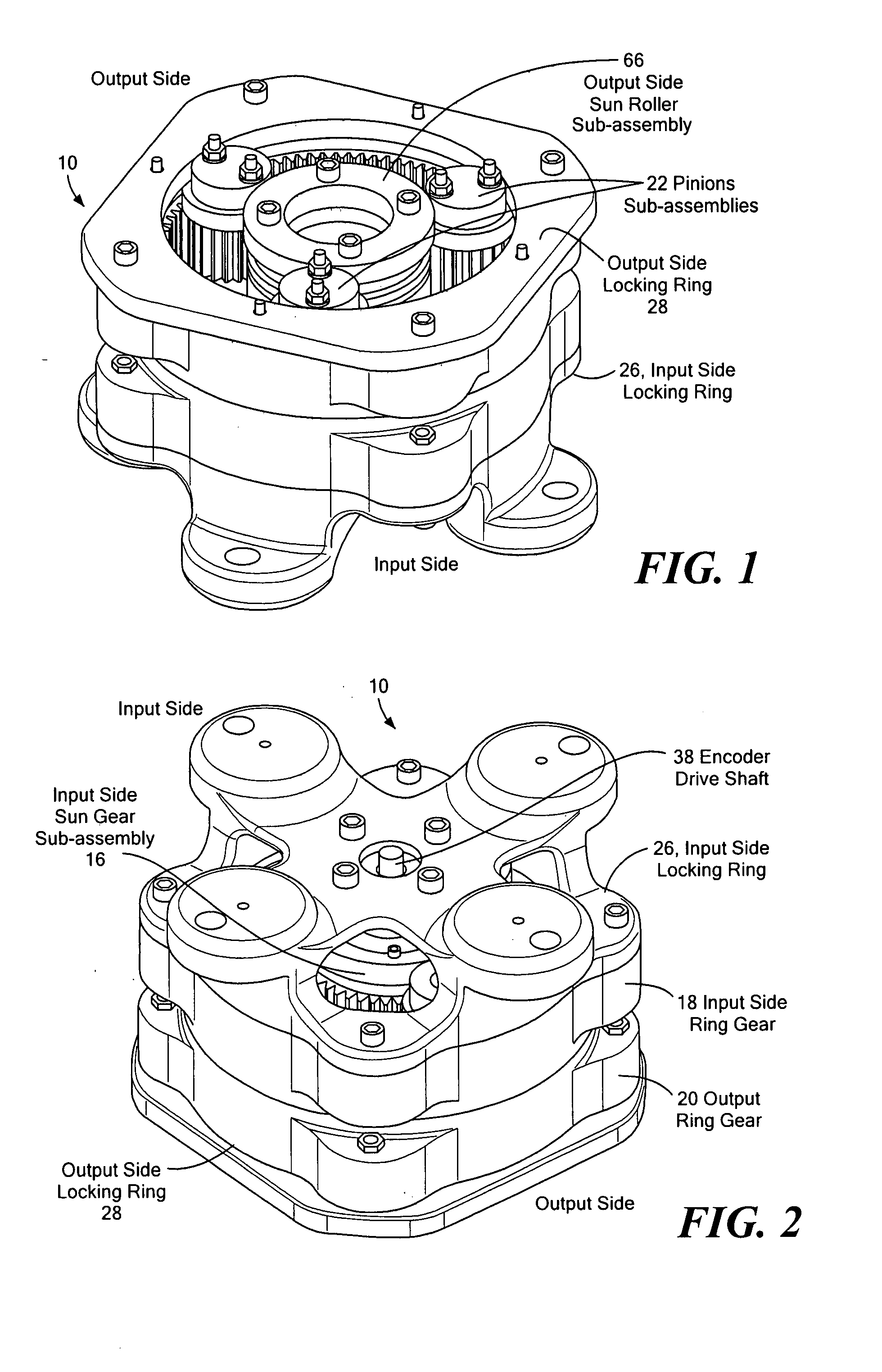
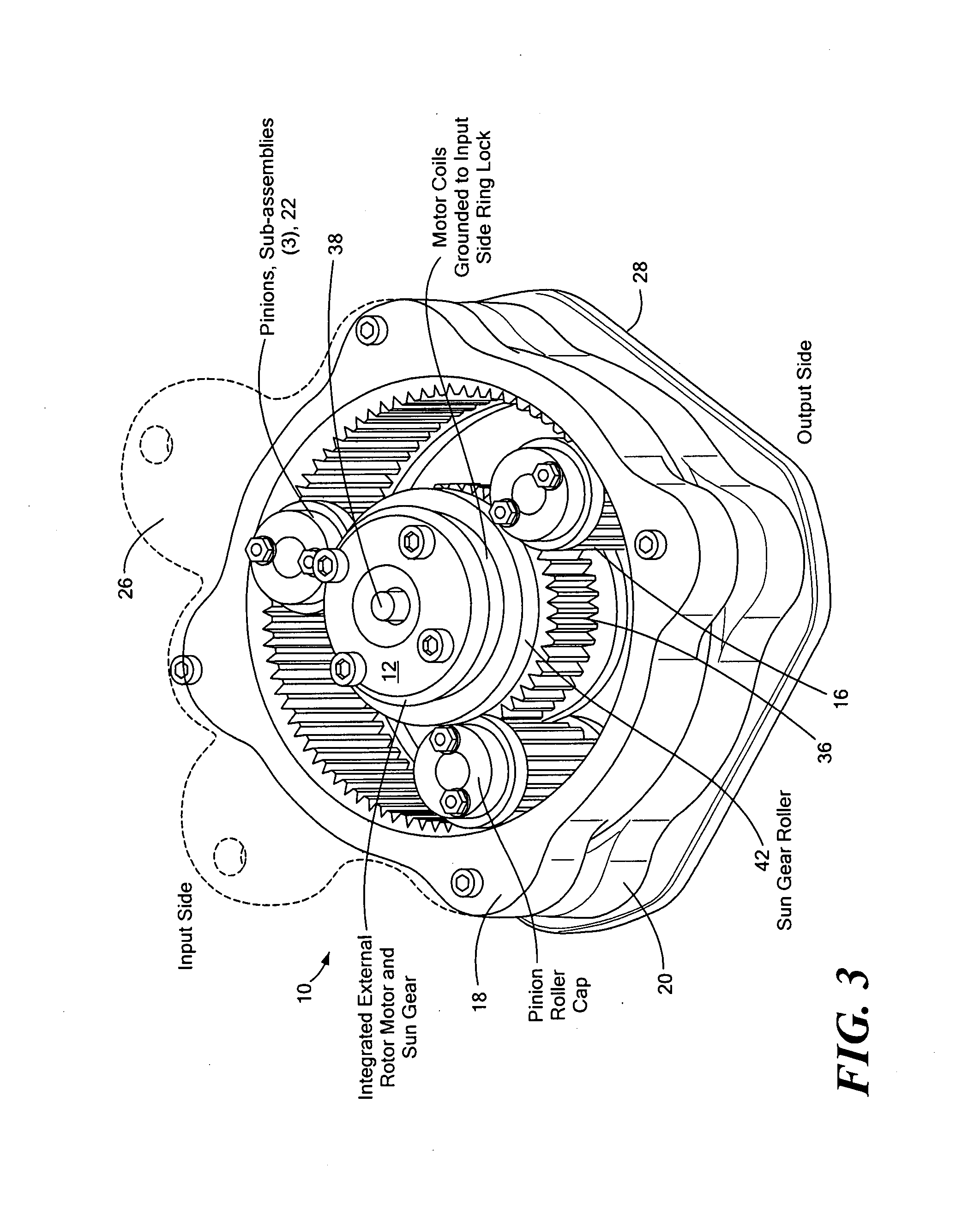
[0062] A first embodiment of a gear bearing drive 10 of the present invention is illustrated in FIGS. 1-13. The gear bearing drive includes an external rotor motor 12 integrated into a gear bearing assembly 14. The gear bearing assembly is a bearingless gear system that places a rolling surface at the pitch diameter of each gear to maintain gearset alignment and to support thrust, radial and bending loads. More particularly, the gear system includes an input side sun gear sub-assembly 16 concentrically surrounded by input side and output side ring gears 18, 20. Several identically-sized pinion gear sub-assemblies 22 interface between the input sun gear sub-assembly 16 and the ring gears 18, 20. The pinion sub-assemblies surround and revolve about the sun gear sub-assembly to connect an input stage to an output stage of the drive. The motor 12 is integrated internally within the sun gear sub-assembly on the input side. The coils 24 of the motor are grounded to the input side of the a...


PUM


Abstract

A gear bearing drive provides a compact mechanism that operates as an actuator providing torque and as a joint providing support. The drive includes a gear arrangement integrating an external rotor DC motor within a sun gear. Locking surfaces maintain the components of the drive in alignment and provide support for axial loads and moments. The gear bearing drive has a variety of applications, including as a joint in robotic arms and prosthetic limbs.

Description

CROSS REFERENCE TO RELATED APPLICATIONS [0001] This application claims the benefit under 35 U.S.C. § 119(e) of U.S. Provisional Application No. 60 / 815,313, filed Jun. 21, 2006, the disclosure of which is incorporated by reference herein.STATEMENT REGARDING FEDERALLY SPONSORED RESEARCH OR DEVELOPMENT [0002] N / A FIELD OF THE INVENTION [0003] The present invention relates to a gear bearing drive and its use in a variety of applications, including prosthetic limbs and robotic arms. BACKGROUND OF THE INVENTION [0004] A gear bearing is a mechanical structure comprising both gear and roller bearing surfaces such that the mechanical power structure and bearing motion control functions are performed without the need for dedicated bearings. Gear bearings take both component and device forms. Gear bearing components can be constructed in many forms, and gear bearing components can be directly interfaced to each other as modules to form gear bearing devices. Gear bearing devices use rolling fri...

Claims


Application Information

Patent Timeline
Patent Type & Authority Applications(United States)
IPC IPC(8): F16H57/08
CPCB25J9/102F16H1/28H02K7/116H02K1/2786H02K7/088F16H57/082H02K1/2791
Inventor WEINBERG, BRIANMAVROIDIS, CONSTANTINOSVRANISH, JOHN M.
Owner NORTHEASTERN UNIV
Why Eureka
Try Eureka