
System and method for policy based control of local electrical energy generation and use

Inactive Publication Date: 2008-02-21
GOPAL RAJEEV +1
View PDF8 Cites 369 Cited by
  • Summary
  • Abstract
  • Description
  • Claims
  • Application Information

AI Technical Summary

Benefits of technology

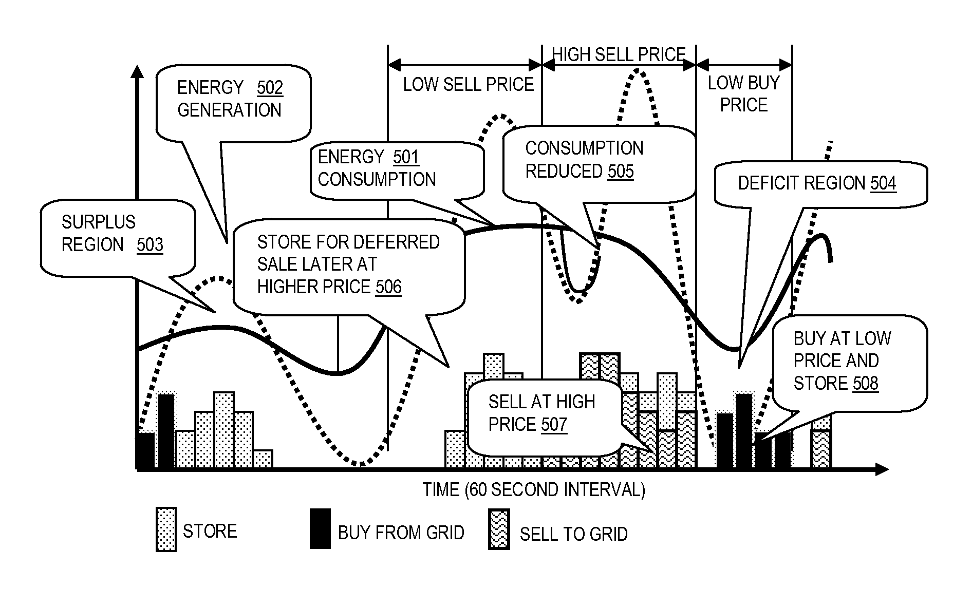
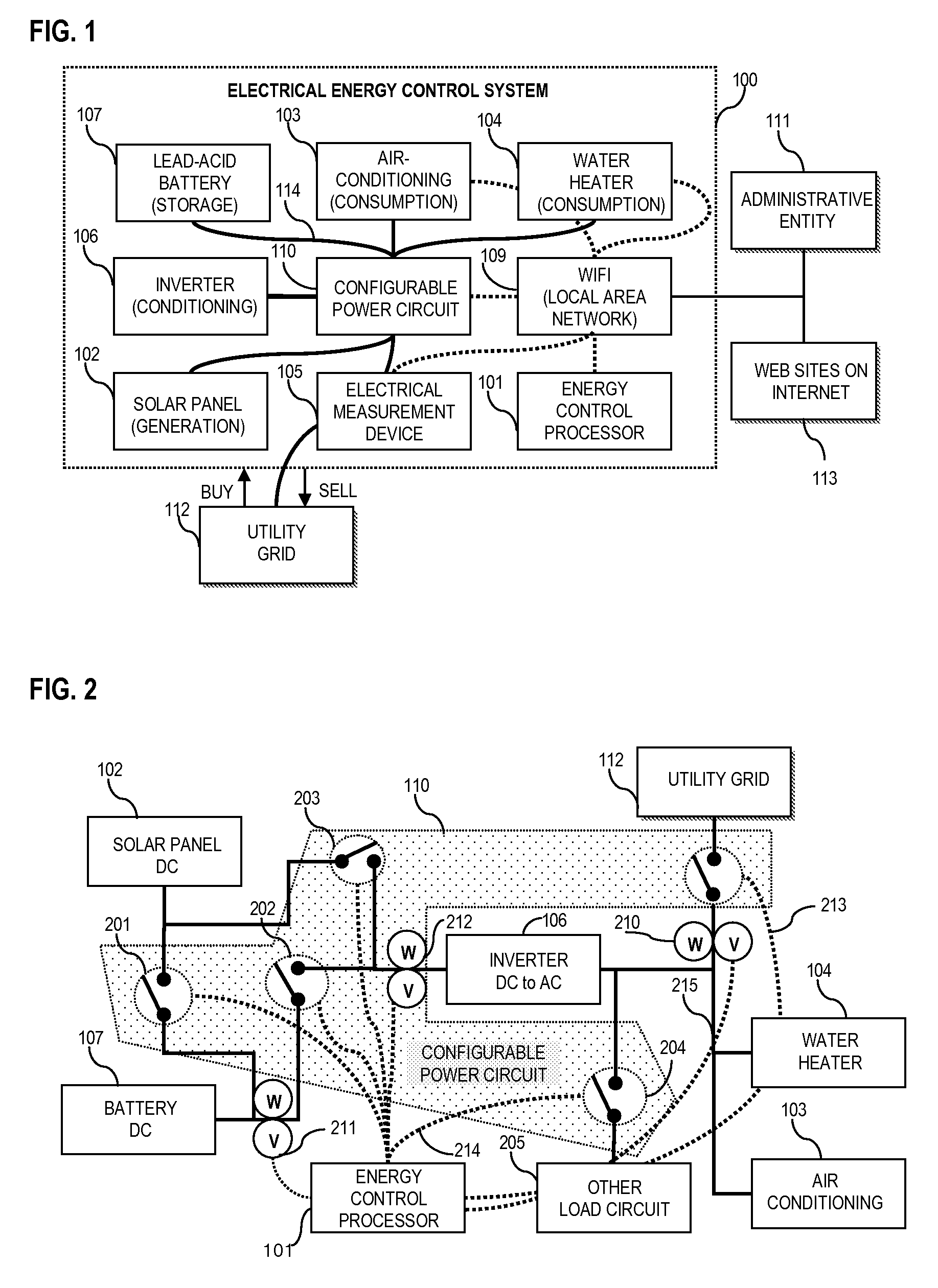
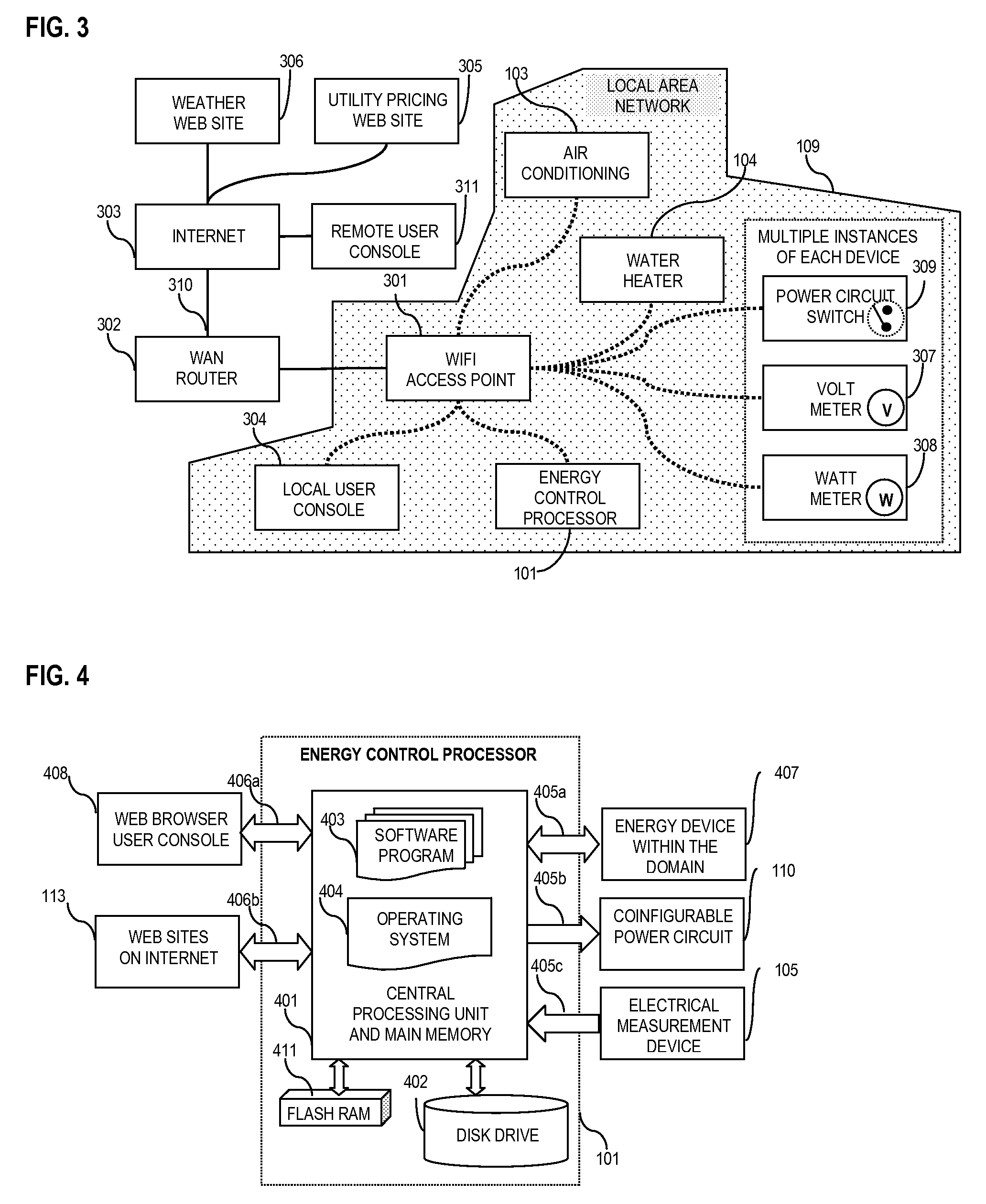
[0014]According to one aspect of the present invention an automated policy driven control system is provided that can make informed decisions affecting the behavior of energy generation and use within a domain. A configurable power circuit with remote controlled switches is used to interconnect various energy generation, storage and consumption devices. A local area network is used to connect the various switches of the power circuit, remote controlled energy devices, and measurement devices to a control processor that provides near real time decisions. To make the invention practical and usable such decisions based on optimization criteria, historical information, current status of the various devices, estimates for future needs, and environmental conditions are made in an efficient and cost effective fashion. This requires an automated approach that can preserve the system state variable values estimated during a long term planning phase and their subsequent near future revisions based on the actual measurement data collected from the devices and external information sources. These estimated state variables provide a bounded region within which a near real time decision process can actually set the optimal energy storage, selling, and purchase values. This innovative hierarchical partitioning of the control method into three phases (long term planning, short term updates, and near real time decision making) makes it feasible to use a general purpose data processing computer for this invention. Thus the system allows the implementation of the control method as software programs running in a control processor for maximum processing and storage flexibility and under the policies specified by the administrative entity responsible for the domain.
[0015]One embodiment of this invention uses solar photo-voltaic panels that are connected to a power circuit within the domain. Based on the location of the domain and jurisdictional stipulations, additional wind turbines can also be added to the power circuit. One or more such generation devices can be connected together to provide the desired voltage and current levels compatible with the needs of the users and various system design criteria. The power circuit itself comprises multiple electronic or electro-mechanical switches at suitable locations thus making the circuit configurable under the control of the optimization method. A specific topology of the circuit, with a set of switches which are on or off, determines the flow of electrical energy possible over the circuit. One or more batteries, for storage, are also connected to the circuit through inverters for converting DC into AC.
[0017]In yet another aspect of this invention, a method is provided for making optimal decisions about energy generation, use, storage, selling, and buying based on specific optimization criteria. One such criterion could to be to enhance the economic value enabled by this invention in reducing the overall cost of energy use within the modular domain. Another criterion could be to provide accurate information related to the type of source used for such energy use such as solar and wind with its environmental implications in maximizing the use of sustainable sources for energy generation. Yet another criterion is related to the level of comfort desired during the use of one or more energy consuming devices such as leisure or work-related lighting, temperature and air-flow control within the domain. These optimization objectives are implemented by the control method which also has access to the generic decision making knowledge, past information about energy decisions made by the method, the current status of various energy devices, weather forecasts, and estimates for energy use and generation for near and long term future in implementing optimal decisions.

Problems solved by technology

It is recognized that besides the costs of fuels, generation plant infrastructure and power distribution grids, the society may also be paying a high long-term price because of a rampant use of fossil fuels as the combustion process may be causing an unprecedented rise in carbon dioxide and other harmful gases in the atmosphere.
Besides adverse health implications because of the pollution associated with fossil fuel burning, most environmental scientists now believe that an excessive rise of atmospheric gases such as carbon dioxide could be causing global warming due to a greenhouse effect and thus resulting in unexpected and increased melting of glaciers and the polar ice caps, and other permanent changes in global climate.
Because of a time-based and seasonal variability in the consumption and generation patterns (such as with solar photo-voltaic panels), it is difficult to estimate the fixed capacity of such generation units for a domain.
However, the traditional generation technologies required economies of scale resulting in the installation of high capacity centralized power generation facilities distributing electrical energy over public utility grid to a large number of individual domains.
A simplistic design of such an energy system will tend to overestimate the size of generation and storage devices resulting in higher initial installation costs and thus would limit the deployment of such solutions.
However, such simplistic decisions normally built into inverters are limited to real time signal processing for AC to DC conversion and are myopic and short-term oriented with respect to energy flow control which can lead to a suboptimal decision in a long term.
Furthermore, these simple local energy generation systems assume the use of a specific energy device with intelligence such as an inverter, and thus are limited with respect to full configurability and connectivity in the power circuit.
Without such an automated control, these decisions will be cumbersome, inefficient, error prone, and expensive to preclude their wide deployment.
It is well known that energy consumption is highest for the devices that generate heat.
For example, a significantly above-average energy consumption by an air-conditioning device compared to its historical performance, after making due seasonal corrections, can point to impending problems in the compressor.

Method used


Image

  • System and method for policy based control of local electrical energy generation and use
  • System and method for policy based control of local electrical energy generation and use
  • System and method for policy based control of local electrical energy generation and use

Examples


Embodiment Construction

[0031]The following describes one embodiment of an automated electrical energy control system for making optimal decisions via the monitoring and control of the various devices within a domain. A domain can be a residential or commercial facility equipped with solar based energy generation, with battery for storage, and optionally connected to the utility grid and optionally connected to the Internet. In this description specific details are documented to facilitate a thorough understanding of the invention. It should be clear that not all of these details are required for a specific embodiment of this invention, but are rather present to provide an example by which a thorough explanation of the mechanizations of the design can be made. In some cases, some well known artifacts, structures, and techniques are described and depicted in diagrams at a block level to ensure that the main facets of the inventions are not obscured.

[0032]The present invention provides an electrical energy c...


PUM


Abstract

A system with automatic control of local generation, consumption, storage, buying, and selling of electrical energy is provided. This automation can be governed by optimization criteria and policies established by the administrative entity responsible for the domain benefiting from this invention. The control method, using a data processing computer, implements the optimization criteria and provides near real time directives for the system. The control program estimates energy generation and consumption, monitors voltage and power levels, configures the power circuit and adjusts device specific controls over a network. Depending on a specific situation, the control program can continue to store extra energy, sell energy for a financial gain, maximize sustainable generation to meet social obligations, or increase consumption for extra comfort. This control program optimizes on multiple time granularities under a variable pricing scheme and environmental conditions, with related information including weather forecasts accessed over the Internet.

Description

BACKGROUND OF THE INVENTION[0001]1. Field of the Invention[0002]The present invention is in the field of control system for local electrical energy generation using solar cells, adjustable energy consumption, energy storage using battery, and selling electrical energy to the grid with the various devices connected over a configurable power circuit within a domain and under the control of software running on a data processing computer. More particularly, the control system utilizes a policy driven hierarchical optimization scheme and employs a local area network for sending configuration commands to the power circuit and devices and for collecting monitoring data. Even more particularly, a control processor running software programs implements the optimization methods and further enhances its optimal decision making capabilities by leveraging information sources for weather forecasts and energy pricing data over the Internet.[0003]2. Discussion of the Background[0004]Modern society c...

Claims


Application Information

Patent Timeline
IPC IPC(8): G06F17/00
CPCG01D4/004Y04S10/54G06Q30/00G06Q50/06H02J3/008Y02B90/242Y02B90/244Y02B90/245Y02B90/248Y04S20/322Y04S20/327Y04S20/40Y04S20/44Y04S20/52Y04S50/10G06Q10/00H02J3/004Y02A30/00Y02B90/20Y04S20/30Y04S10/50G01D2204/12G01D2204/30G01D2204/14G01D2204/16
Inventor GOPAL, RAJEEVGOPAL, ROHIT
Owner GOPAL RAJEEV
Learn More