

Method and apparatus for verifying the authenticity of an item by detecting encoded luminescent security markers
a luminescent security marker and encoded technology, applied in the field of apparatus for verifying the authenticity of optical security marks, can solve the problems of not fully protecting '547 system does not fully protect against counterfeit markers emitting at these wavelengths, and 547 application does not address some practical problems, etc., to achieve convenient portability, minimal optics, and easy alignment
- Summary
- Abstract
- Description
- Claims
- Application Information
AI Technical Summary
Benefits of technology
Problems solved by technology
Method used
Image

Examples
example 1
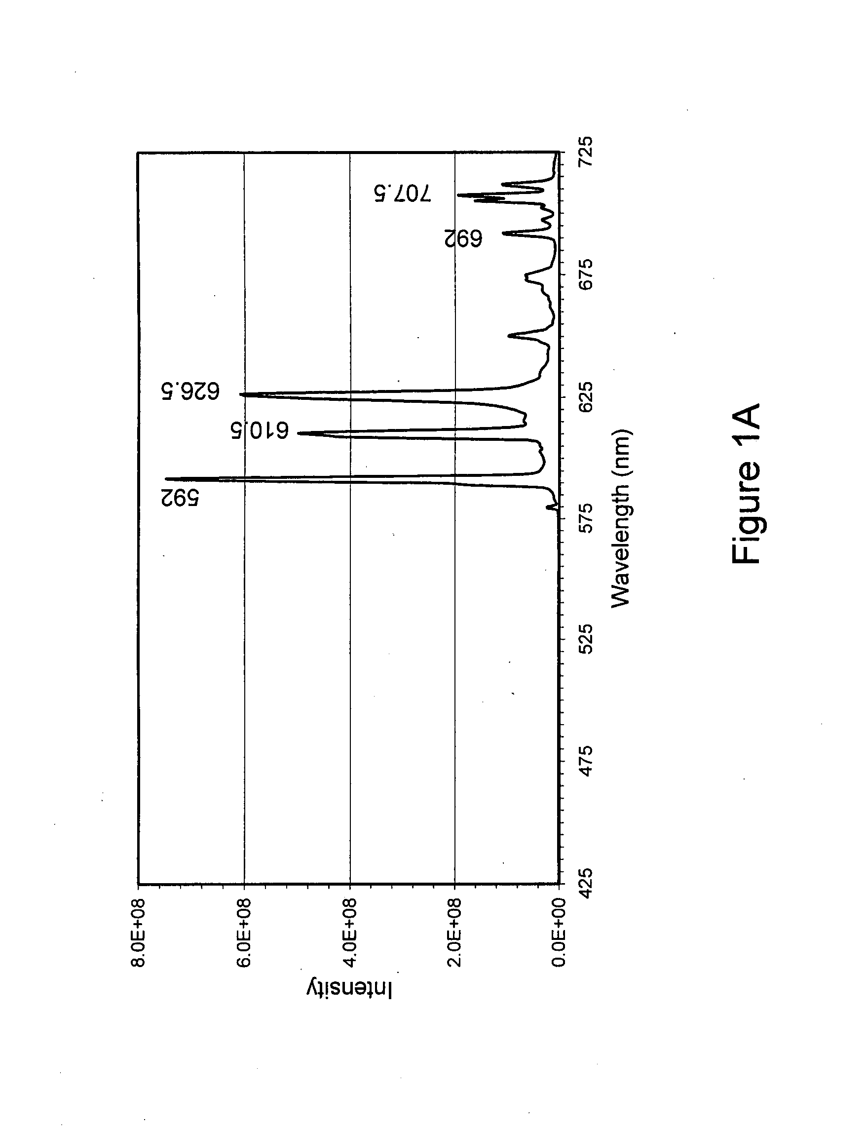
Luminescent Material Having a Spectrum with 3 Peaks (FIG. 1A)
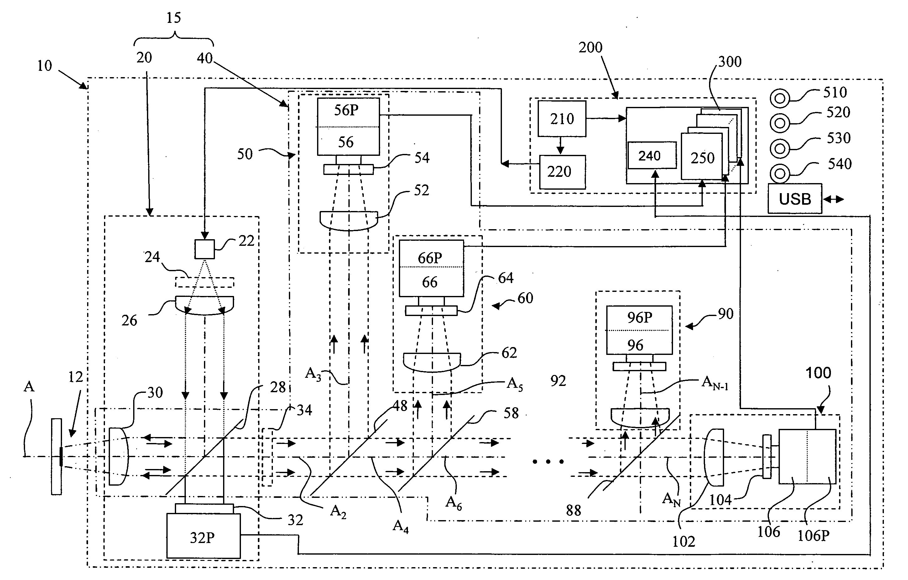
[0080]An apparatus 10 having an arrangement in accordance with FIG. 2, having four photodetector assemblies might be used to determine the authenticity of an item bearing a luminescent security mark with an emission spectrum like that shown in FIG. 1A. In such an apparatus, the band-pass filter 54 of photodetector assembly 50 is centered at 589 nanometers and has a full-width at half-maximum (FWHM) transmission of 10 nanometer so that it passes the wavelength band 584-594 nanometers, the band-pass filter 64 of photodetector assembly 60 passes the wavelength band 605-615 nanometers and the band-pass filter 74 of photodetector assembly 70 passes the wavelength band 689-699 nanometers. Additionally, for this spectrum, a photodetector assembly 80 having a band-pass filter 88 might pass light between 540 and 570 nanometers to verify the absence of appreciable light energy in this wavelength range.
example 2
Security Marks with Two Luminescent Materials Demonstrating the Use of Wavelength-Specific Beamsplitters (48, 58) to Separate Eu3+ and Tb3+ Luminescence
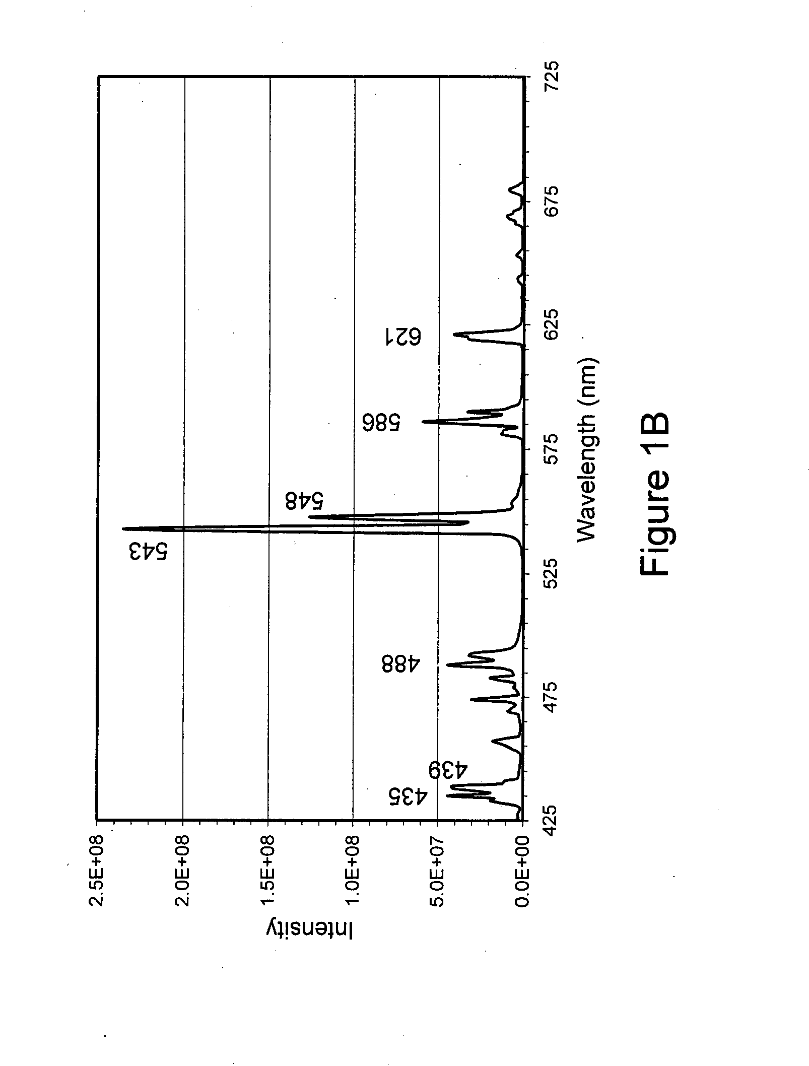
[0081]A series of “Tb3++Eu3+” luminescence spectra were “synthesized” by mathematically adding a first spectrum (FIG. 1A) of Kasei Optonix (Y,Gd)BO3:Eu (sold as KX-504A) excited with 394 nanometer light and a second spectrum (FIG. 1B) of GTE Sylvania Gd2O2S:Tb (Type 2611) excited with 377 nanometer light, each spectrum multiplied by a variable factor to simulate different mixing ratios (as specified in the second and third columns of Table 1 below). The two starting spectra were measured using a SPEX® Fluorolog-3® spectrometer with excitation and emission resolution set to 1 nanometer. The resulting synthesized luminescence spectra of this hypothetical mixture (as shown in FIG. 1C) were convolved with the reflectivity spectral responses of two filters selected to separate the green Tb emission from the red Eu emission. The green filt...
example 3
[0111]A commercial single-phase lock-in amplifier (EG&G Princeton Applied Research Model 5209) was used to analyze the output signals from the Si photodiode circuitry. The LED was electronically modulated using a Stanford Research DG535 pulse generator. The modulated excitation waveform is square-wave, with an independently variable pulse width and pulse frequency. Since a lock-in amplifier with an electronic band-pass filter centered at the LED modulation frequency is used, only the fundamental cos (ωt) component of the Fourier series expansion of the signal resulting from the square-wave excitation is detected. It should be appreciated that a somewhat larger signal could be obtained by modulating the LED output sinusoidally, so that the entire signal appears at a single modulation frequency. The data shown were collected with a lock-in time constant of one second (selected to meet a criterion of a one second read time), corresponding to a detection bandwidth o...
PUM
 Abstract
Description
Claims
Application Information