
Method for Producing Graphite Film, and Graphite Film Produced By the Method

a graphite film and graphite technology, which is applied in the direction of electrolysis components, electrolysis equipment and processes, and semiconductor/solid-state device details, etc., can solve the problems of insufficient graphite as a heat radiation material for use in a recent electronic device emitting a drastically large amount of heat, damage to the film is easily caused, and the effect of high quality

Active Publication Date: 2008-02-28
KANEKA CORP
View PDF6 Cites 20 Cited by
  • Summary
  • Abstract
  • Description
  • Claims
  • Application Information

AI Technical Summary

Benefits of technology

[0035] In the conventional method in which a sintered product prepared from a carbon-source powder and a caking additive is heated by electrification so as to graphitize the sintered product, the sintered product has an electric conductivity that is not uniform. This causes the sintered product to be heated unevenly. Thereby, the conventional method cannot attain a graphite film of a high quality. On the other hand, the present invention can provide a graphite film of a high quality as explained below.
[0036] The present invention, which does not adopt the conventional atmospheric heating or heating under reduced pressure, includes the step of holding the raw material film in a vessel being directly electrifiable by voltage application; and graphitizing the raw material film in the vessel by applying a voltage on the vessel so as to carry out electrification. This results in voltage application on and electrification of the raw material film thereby causing heat generation of the raw material film. As a result, an electric resistance is lowered as the raw material film is carbonated. As the electric resistance is lowered, a current flows through the raw material film. Due to the resultant Joule heat, heat is generated in the raw material per se. As a result, an inside and a surface portion of the film are uniformly heated. The electrifiable vessel also heats the film from film's surrounding sufficiently and uniformly. Therefore, the present invention makes it possible to provide a graphite that is more excellent in electric conductivity and heat conductivity.
[0037] Even with a raw material film of the order of 225 μm in thickness, which is thicker than in the conventional art, the film is heated from the inside, surface portion, and the surroundings thereof in the present invention. Thus, the surface portion and the inside of the film are graphitized substantially simultaneously. A graphite layer, which will prevent generation of decomposition gas, will not be formed in the surface layer. This makes it easy for the decomposition gas to escape from the inside of the film. Thus, the film will not be damaged by the decomposition gas. Therefore, the present invention can provide a thick graphite film that is excellent in the electric conductivity and heat conductivity.
[0038] Moreover, especially by using a polyimide film, particularly, a polyimide film of the production method according to the present invention and / or, a polyimide film that is designed to have molecules that are highly aligned with easy to have a specific birefringence, it is possible to attain a graphite film that is more excellent in the electric conductivity and heat conductivity than the conventional art.
[0039] The present invention may be arranged such that a plurality of the electrifiable vessels (A) in which a raw material film is held are held in an electrifiable vessel (B) and they are electrified as a whole. With this arrangement, the graphite films produced in the vessels (A) will have a quality uniformly.

Problems solved by technology

The electric conductivity and heat conductivity of the graphite thus produced are inferior to those of the graphite produced by using the polymer thermolysis method.
However, the heat conductivity of such conventional graphite obtained by heating a polymeric film under an inert atmosphere and / or reduced pressure was found to be insufficient, so that the graphite was insufficient as a heat radiation material for use in a recent electronic device emitting a drastically large amount of heat.
However, in the conventional polymer thermolysis method, damage to the film is easily caused.
In the polymer thermolysis method in which the heating is carried out under the inert atmosphere, the raw material film is heated from its surface, so that graphitization progressed unevenly between the inside of the film and the surface thereof.
As a result, the film attains merely a low overall heat conductivity.
However, with such heating, the raw material film is heated unevenly, so that graphitization progressed unevenly.
This results in a low heat conductivity of the film.
Further, due to the graphitization progressing from the surface of the raw material film, it is difficult for decomposition gas to get out from the inside of the raw material film, especially in cases where the raw material film is a thick one.
The decomposition gas emitted out therefrom with such difficulty causes damages to the film.
Even in cases where the film was not broken, graphitization does not progress sufficiently in the inside of the film as compared with that in a thin film.
Thus, the film has a heat conductivity much inferior to that of the thin film.
The electric conductivity of the sintered substance is uneven, so that a current unevenly flew in the sintered substance.
Accordingly, temperature rose locally therein, with the result that the sintered substance is graphitized unevenly and therefore is cracked and broken with ease.
Therefore, the graphite thus obtained by using this conventional method has heat conductivity and electric conductivity much inferior to those of the graphite film obtained by heating the polymeric film.
Further, in production of a plurality of sintered substances, displacement of sintered substances likely occur during heating.
Such displacement would deteriorate properties thereof.
With this, graphite having no crack can be obtained but the graphite has much inferior heat conductivity and electric conductivity.
Moreover, when the method of fixing raw material films with an adhesive agent is adopted for acquirement of graphite in the form of a plurality of films, the adhesive agent causes deterioration of quality of the graphite.

Method used


Image

  • Method for Producing Graphite Film, and Graphite Film Produced By the Method
  • Method for Producing Graphite Film, and Graphite Film Produced By the Method
  • Method for Producing Graphite Film, and Graphite Film Produced By the Method

Examples


example 1

[0270] Each polyimide film A was sandwiched between graphite plates and heated in an electric furnace under nitrogen atmosphere by increasing a temperature up to 1000° C. The heat treatment was then carried out at a temperature of 1000° C. for 1 hour, and films were carbonized. These carbonized films are referred to as carbonized films A′.

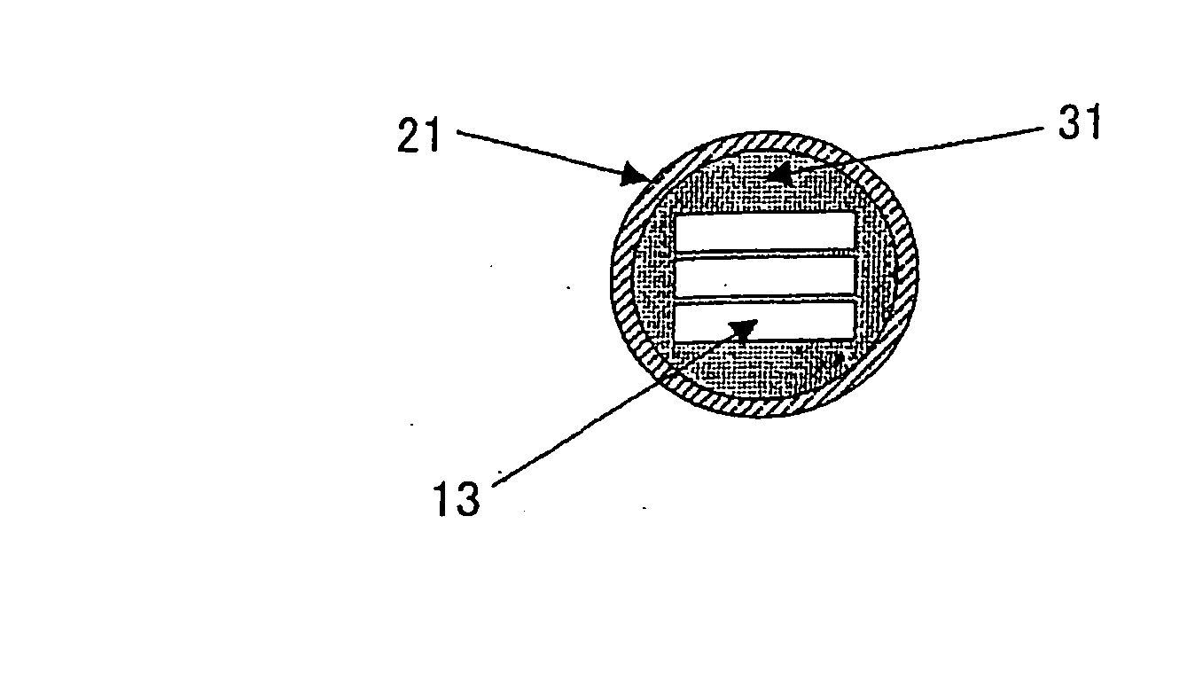
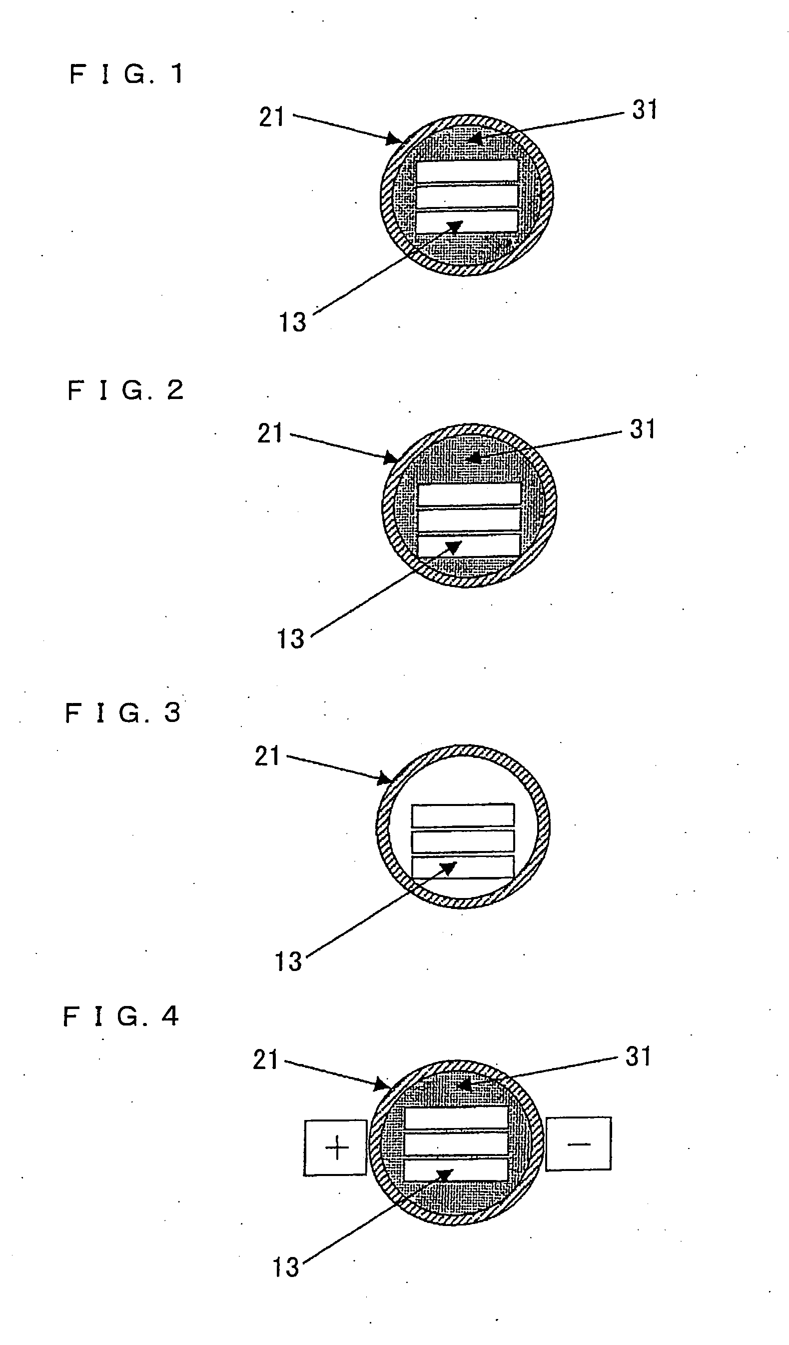
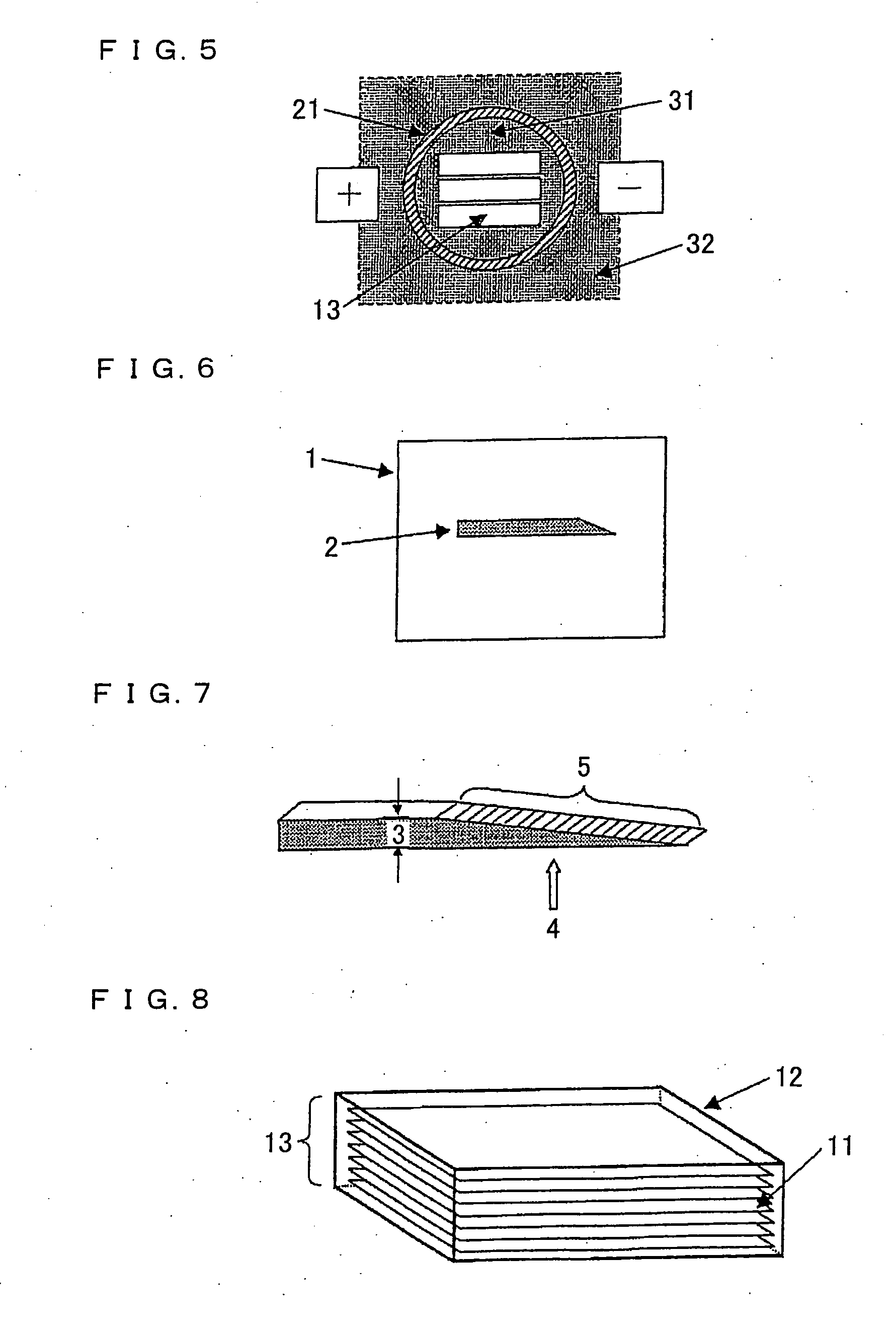
[0271] The obtained carbonized films A′ sandwiched between the flat and smooth graphite plates having a shape of 6 cm×width 6 cm×thickness of 5 mm were held in a graphite vessel having the shape of a rectangular solid. The vessel including the carbonized films A′ was then covered by carbon powder essentially consisting of coke, and heated by directly electrifying the entire vessel and carbon powder to heat the film up to 3000° C., not by heat application under atmosphere. As such, graphite films were manufactured.

example 2

[0272] Polyimide films B were used. As in Example 1, graphite films were manufactured by carbonizing the polyimide films B and then electrifying the carbonized films B′.

example 3

[0273] Polyimide films C were used. As in Example 1, graphite films were manufactured by carbonizing the polyimide films C and then electrifying the carbonized films C′.


PUM

PropertyMeasurementUnit
angleaaaaaaaaaa
angleaaaaaaaaaa
thicknessaaaaaaaaaa

Abstract

A graphite film excelling in heat conductivity, especially, a graphite film of high heat conductivity that even when its thickness is large, would not suffer damage by heat treatment. There is provided a process for producing a graphite film, including graphitizing a raw material film of a polymer film and / or carbonized polymer film, characterized by including (i) holding the raw film in a vessel capable of direct passage of current through voltage application and (ii) applying voltage to the vessel to thereby induce electrification so that graphitization is carried out. There is further provided a process for producing a graphite film, characterized by including the step of holding the raw material film in vessel (A) being electrifiable, subsequently holding the resultant vessel (A) in vessel (B) being electrifiable and effecting current passage through the whole so that graphitization is carried out.

Description

TECHNICAL FIELD [0001] The present invention relates to (i) a method for producing a graphite film used as a heat radiation film, and (ii) a graphite film produced by using the method. BACKGROUND ART [0002] A polymer thermolysis method (Patent Citations 1 and 2) is known as a method for obtaining a graphite film excellent in electric conductivity and heat conductivity. In the polymer thermolysis method, a heating treatment is given to a polymeric film under (i) an inert atmosphere such as argon or helium, and / or (ii) reduced pressure. An example of such a polymeric film is a film made of polyoxadiazole, polyimide, polyphenylenevinylene, polybenzimidazole, polybenzoxazole, polythiazole, polyamide, or the like. [0003] Meanwhile, a method (described in Patent citation 3) is known as a mass-production method for producing, with high productivity, a large volume of graphite for use in a shaft bearing, a seal, a melting pot, a heating element, and the like. In the method, a mixture of (i)...

Claims


Application Information

Patent Timeline
Patent Type & Authority Applications(United States)
IPC IPC(8): C01B31/04C25B1/00
CPCC01B31/04H01L23/373H01L2924/0002H01L2924/00C01B32/20C01B32/205
Inventor NISHIKAWA, YASUSHIWAKAHARA, SHUHEIMURAKAMI, MUTSUAKI
Owner KANEKA CORP
Features
  • Generate Ideas
  • Intellectual Property
  • Life Sciences
  • Materials
  • Tech Scout
  • Unparalleled Data Quality
  • Higher Quality Content
  • 60% Fewer Hallucinations
Learn More