Original data producing method and original data producing program
- Summary
- Abstract
- Description
- Claims
- Application Information
AI Technical Summary
Benefits of technology
Problems solved by technology
Method used
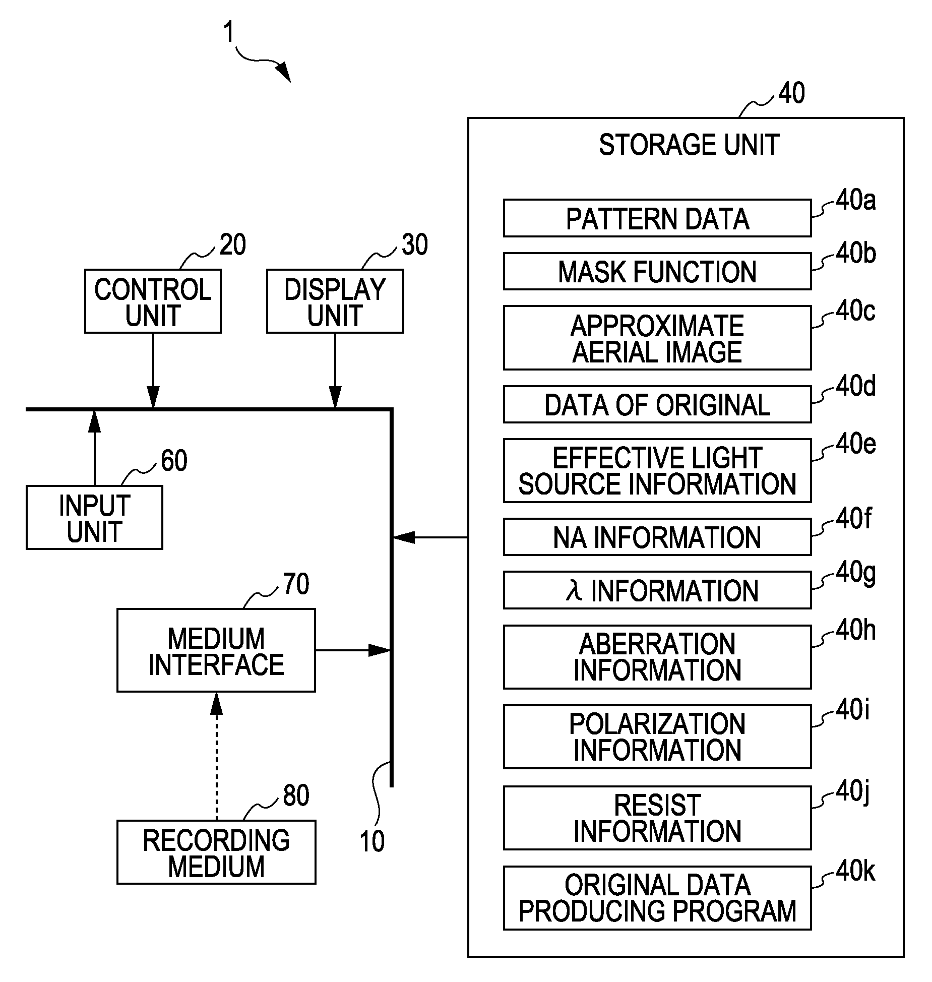
Image

Examples
first embodiment
[0099]A method for deciding the mask pattern and a method for producing the original data based on the approximate aerial image are described in this first embodiment.
[0100]In this first embodiment, an exposure apparatus is assumed to have NA of 0.73 and the wavelength of 248 nm. Further, it is assumed that the projection optical system is aberration free, the illumination light is not polarized, and the resist is not taken into consideration. A pattern as a target to be formed on a wafer (hereinafter referred to as a “target pattern”) is an isolated contact hole with a diameter of 120 nm.
[0101]Because the exposure apparatus can take various values of NA and λ, it is convenient to normalize a pattern size in terms of (λ / NA). For example, when λ is 248 nm and NA is 0.73, 100 nm corresponds to 0.29 based on the normalization. In this specification, such normalization is called k1 conversion.
[0102]When λ is 248 nm and NA is 0.73, 120 nm corresponds to about 0.35 by the k1 conversion. I...
second embodiment
[0110]In the second embodiment, a description is given of a method for inserting optimum auxiliary patterns when the target pattern is made up of a plurality of contact hole patterns.
[0111]As discussed above in the first embodiment, the imaging performance of one contact hole is improved by utilizing Y0,0(x, y). The calculation in the case of one contact hole can also be applied in the same manner to the case including a plurality of contact hole patterns.
[0112]The information for calculating the approximate aerial image except for the mask function 40b is the same as that in the first embodiment. The target pattern is given by three contact hole patterns each having a diameter of 120 nm. Centers of those contact hole patterns are positioned at (0, 0), (320, 320), and (640, −350).
[0113]As shown in FIG. 8A, the mask function 40b is set as a function representing three sets of pattern data (light-transmissive portions) each having a 120-nm square shape. Center positions of the pattern...
third embodiment
[0121]In the third embodiment, a description is given of the case where the target pattern is a rectangular contact hole pattern or a line pattern. The information for calculating the approximate aerial image except for the mask function 40b is the same as that in the first embodiment except for the effective light source information 40e and the mask function 40b. The target pattern is a 120-nm isolated line.
[0122]The third embodiment is described as a method for deciding a mask pattern and a method for producing original data in connection with the case of bright field with dark patterns (so-called clear field mask), in which a pattern is formed corresponding to an area where the intensity of a light projected onto a wafer is not larger than a certain threshold. In that case, for example, a resist coated over a substrate is partly left by development in an area which has been exposed to the light intensity not larger than the threshold, whereby a pattern is formed corresponding to ...
PUM
 Abstract
Description
Claims
Application Information
 - Generate Ideas
- Intellectual Property
- Life Sciences
- Materials
- Tech Scout
- Unparalleled Data Quality
- Higher Quality Content
- 60% Fewer Hallucinations
Browse by: Latest US Patents, China's latest patents, Technical Efficacy Thesaurus, Application Domain, Technology Topic, Popular Technical Reports.
© 2025 PatSnap. All rights reserved.Legal|Privacy policy|Modern Slavery Act Transparency Statement|Sitemap|About US| Contact US: help@patsnap.com