
Imaging lens

a technology of imaging lens and spherical lens, which is applied in the field of imaging lens, can solve the problems of insufficient study of inability to study temperature characteristics and cost, and inability to meet the needs of use, etc., and achieve excellent temperature characteristics, reduced size, and high performance.

Active Publication Date: 2008-03-06
TIANJIN OFILM OPTO ELECTRONICS CO LTD
View PDF6 Cites 25 Cited by
  • Summary
  • Abstract
  • Description
  • Claims
  • Application Information

AI Technical Summary

Benefits of technology

[0006]An object of an illustrative, non-limiting embodiment of the invention is to provide an imaging lens which has excellent temperature characteristics, a reduced size, and high performance while the cost is suppressed.
[0008]In the imaging lens, the lens shape and the refractive power can be adequately set by the lens configuration in which a relatively small number of lenses, i.e., four lenses are used as a whole, and hence miniaturization and high performance can be realized. Furthermore, the second lens is provided with a relatively large power, and configured by a spherical glass lens. Therefore, the temperature characteristics can be advantageously set while suppressing the cost. Particularly, conditional expression (1) is satisfied so that the focal length of the second lens is substantially equal to or similar to that of the whole system. Even when the other lenses are aspherical plastic lenses, therefore, the positive and negative refractive powers of the lenses are cancelled each other, and a performance which is advantageous to the temperature characteristics can be obtained.
[0010]According to the configuration, the power balance among the lenses is optimized, and hence miniaturization and high performance can be realized more readily.
[0012]According to the configuration, the shape of the first lens is optimized, and it is advantageous to correction of various aberrations.
[0014]According to the configuration, the shapes of the third and fourth lenses are optimized, and it is advantageous to correction of various aberrations. The back focus which is required for placing a cover glass and the like can be easily ensured.

Problems solved by technology

When only plastic lenses are used, however, there may be an issue in temperature characteristics.
When an aspherical lens is configured by a glass molded lens, however, the cost is inevitably largely increased.
In the imaging lens disclosed in JP-A-2000-180719, the temperature characteristics and the cost are not sufficiently studied, and also the compactness is not sufficiently considered.

Method used


Image

  • Imaging lens
  • Imaging lens
  • Imaging lens

Examples


examples

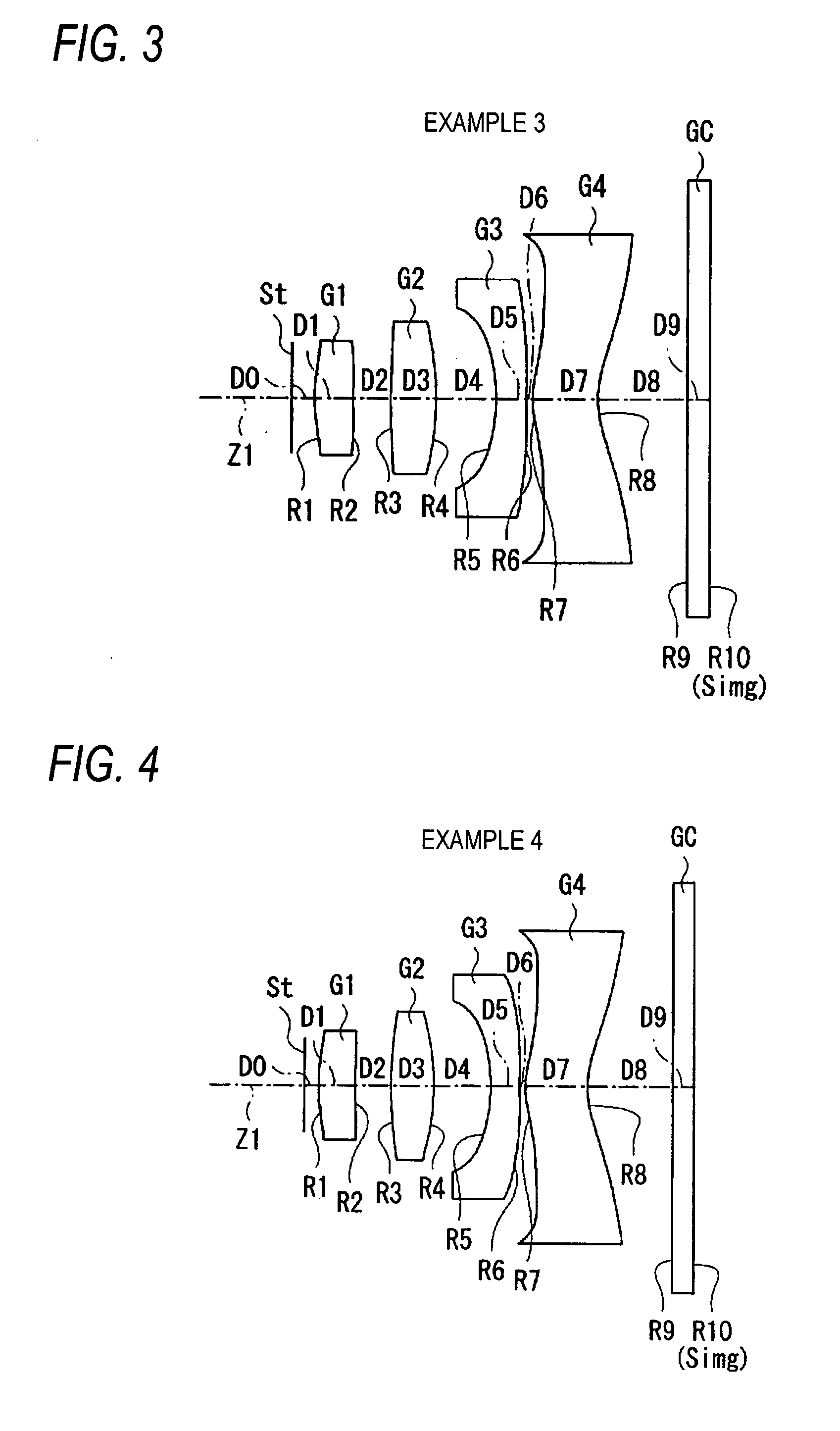
[0055]Next, specific numerical examples of the imaging lens of the embodiment will be described. Hereinafter, first to fifth numerical examples will be collectively described.

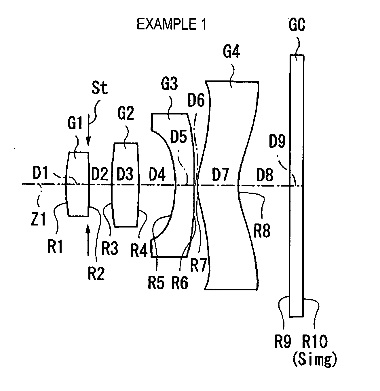
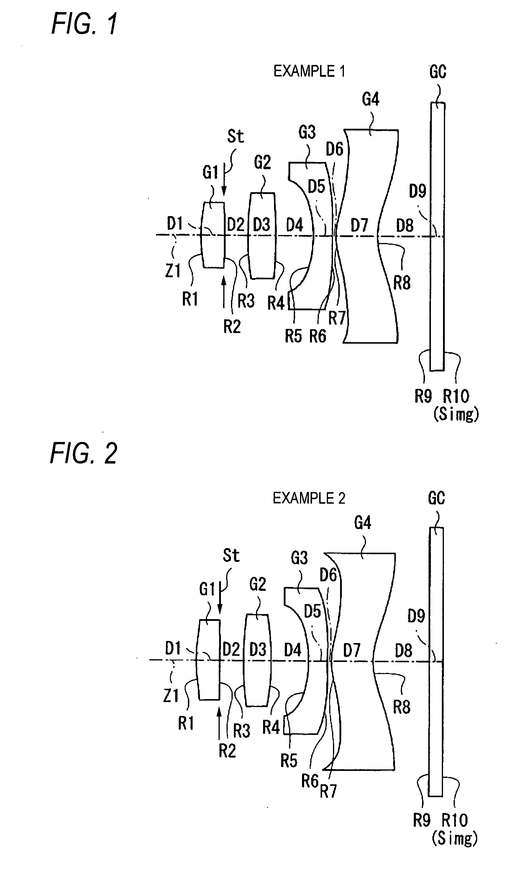
[0056]FIGS. 6A, 6B show specific lens data corresponding to the configuration of the imaging lens shown in FIG. 1, as Example 1. FIG. 6A shows basic lens data, and FIG. 6B shows data relating to an aspherical surface. In the column of the surface number Si in the lens data shown in FIG. 6A, the number of an i-th (i=1 to 10) surface which is numbered in such a manner that the surface of a component that is closest to the object side is set as the first surface, and the number is more sequentially increased as further advancing toward the image side is shown. In the column of the radius of curvature Ri, the value (mm) of the radius of curvature of the i-th surface counted from the object side is shown in correspondence to the reference character Ri used in FIG. 1. Also in the column of the surface separation Di, ...


PUM


Abstract

An imaging lens is provided and includes: in order from an object side of the imaging lens, a first lens having a positive refractive power; a second lens having a positive refractive power and being a spherical glass lens having a convex surface on an image side thereof; a third lens having a negative refractive power and having a concave surface on the object side in the vicinity of an optical axis thereof; and a fourth lens having a positive refractive power and having a meniscus shape in the vicinity of the optical axis thereof, a convex surface in the meniscus shape being directed to the object side, the imaging lens satisfying a specific condition.

Description

BACKGROUND OF THE INVENTION[0001]1. Field of the Invention[0002]The present invention relates to an imaging lens to be mounted on an imaging apparatus using an imaging device such as a CCD (Charge Coupled Device) or a CMOS (Complementary Metal Oxide Semiconductor), a digital still camera, a camera-equipped portable telephone, or a personal digital assistance (PDA).[0003]2. Description of Related Art[0004]In a recent imaging device such as a CCD or a CMOS, miniaturization and increase of pixels are highly advancing. Therefore, also the body of an imaging apparatus, and lenses mounted thereon are requested to be further miniaturized and have a higher performance. An imaging lens to be mounted on, for example, a camera-equipped portable telephone is often configured by three lenses. In order to cope with an increased pixel number, however, the number of lenses tends to increase. In order to realize miniaturization and high performance by a reduced number of lenses, furthermore, an asph...

Claims


Application Information

Patent Timeline
IPC IPC(8): G02B9/34
CPCG02B13/18G02B9/34
Inventor SATO, KENICHI
Owner TIANJIN OFILM OPTO ELECTRONICS CO LTD
Learn More