Radar level gauging

a level gauging and radar technology, applied in the direction of level indicators by physical variables, liquid/fluent solid measurements, engine lubrication, etc., can solve the problems of contaminated contents of the tank, inability to detect the surface echo, and inability to accurately measure the level of the gauging process. , to achieve the effect of sufficient accuracy

Inactive Publication Date: 2008-03-13
ROSEMOUNT TANK RADAR
View PDF22 Cites 18 Cited by
  • Summary
  • Abstract
  • Description
  • Claims
  • Application Information

AI Technical Summary

Benefits of technology

[0009]It is therefore an object of the present invention to overcome at least some of the above problems, and provide an improved method for locating a

Problems solved by technology

In some situations, notably when gauging a product that is highly transparent such as a liquid gas, the bottom of the tank will cause a relatively strong reflection, sometimes strong enough to make detection of the surface echo difficult.
Relying on an approximated value when using the method in U.S. Pat. No. 5,438,867 may therefore lead to inaccuracy in the level gauging process.
Further, in some cases the contents of the tank are contaminated, for example by water that has entered the tank.
This interface w

Method used


Image

  • Radar level gauging
  • Radar level gauging
  • Radar level gauging

Examples


Embodiment Construction

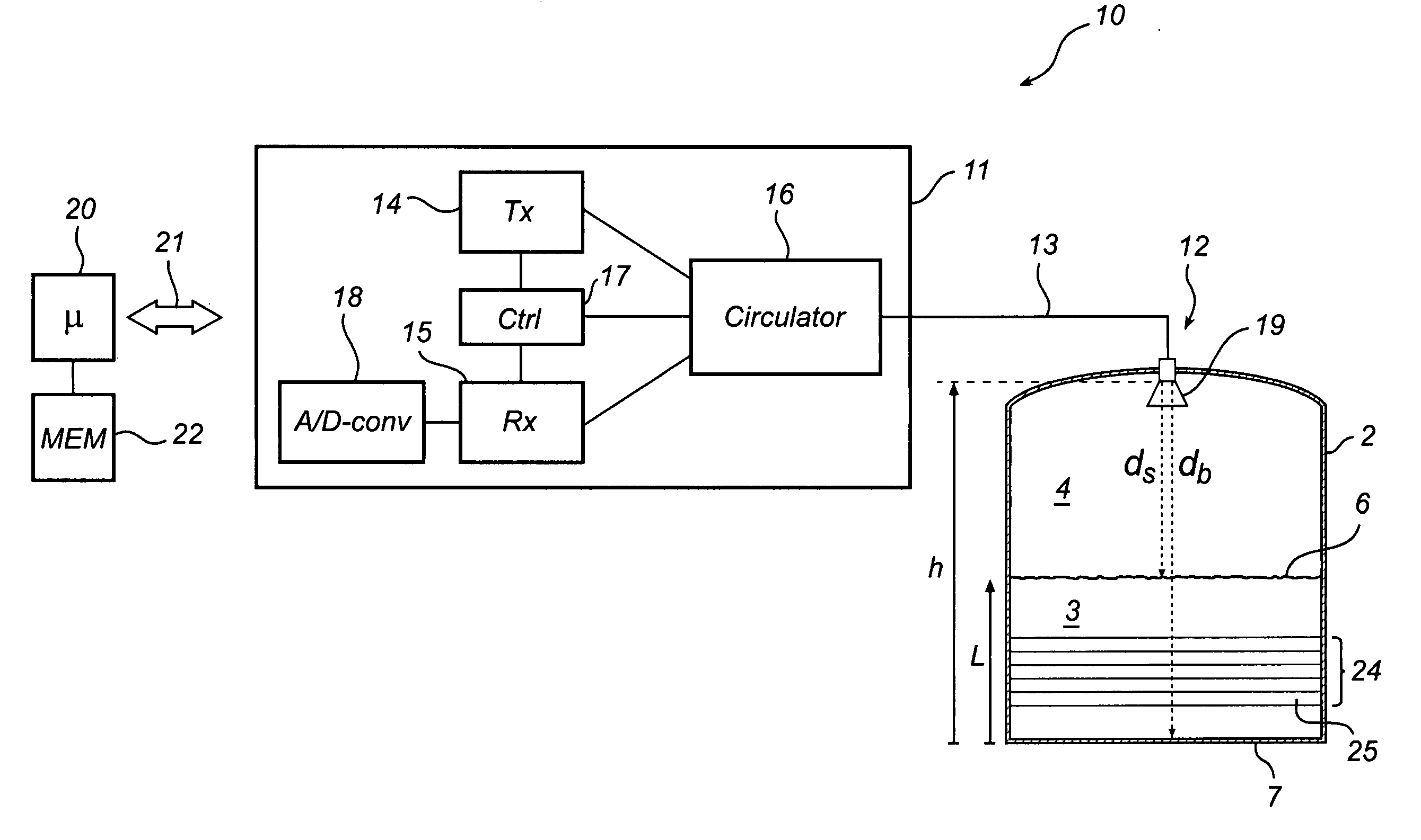
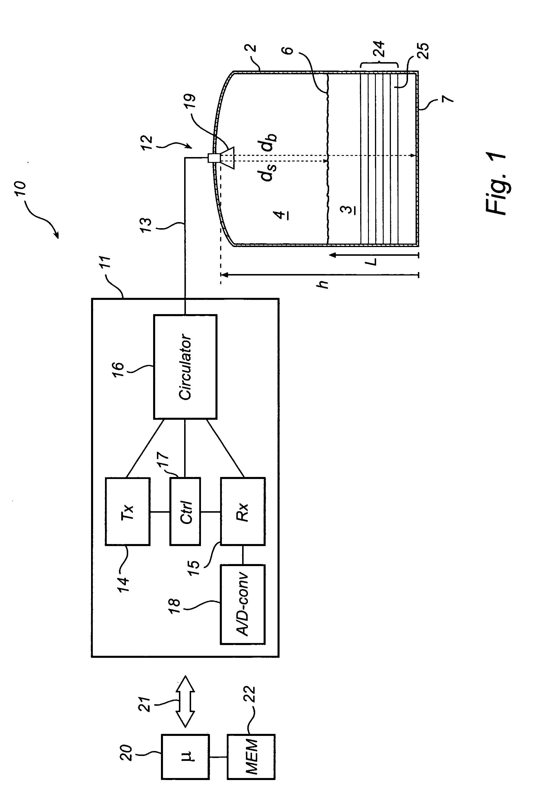
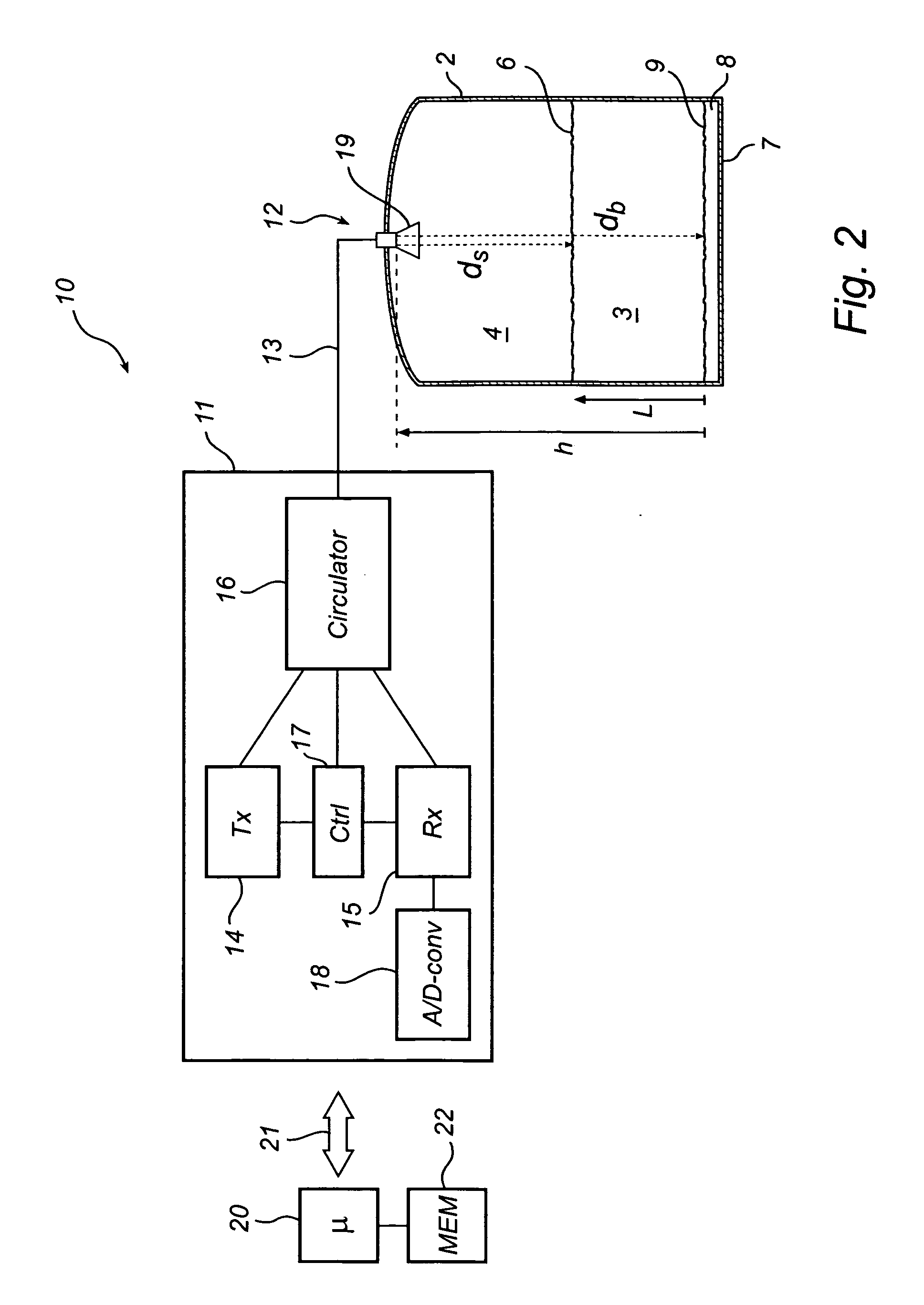
[0032]FIG. 1 shows a schematic block diagram of a radar level gauge (RLG) 10 mounted in a tank 2, in which a method according to the present invention can advantageously be implemented. The gauge 10 is arranged to perform measurements to determine a process variable, here the level L of a product 3 stored in the tank 2. The product can be an oil product, such as e.g. crude oil, a liquid petroleum gas (LPG), a liquid natural gas (LNG), other liquid hydrocarbons, or liquids in general which are at least partially transparent to microwaves. Propane and butane are two typical gases stored in condensed form as liquids.

[0033]The RLG 10 comprises a microwave controller 11, a microwave emitter / receiver 12, and a signal transfer medium 13 connecting the emitter / receiver 12 to the controller 11. The controller 11 can comprise a transmitter 14, a receiver 15, a circulator 16 and any control circuitry 17 required to manage these components. Further, the controller 11 can comprise an A / D-convert...


PUM


Abstract

A method for determining at least one process variable of a product contained in a tank, comprising acquiring a set of distance pairs, each pair including a first distance measure of the distance to a surface of the product and a second distance measure of the distance to a fixed location in the tank beneath the product surface, each distance pair being acquired by emitting microwaves into the tank, and allowing them to propagate towards the product, receiving reflected waves from the tank, including an echo from the product surface and an echo from the fixed location, and determining said first and second distance measure based on the emitted and received microwaves. The distance pairs are used to calculate at least one of the actual distance to the fixed location and a delay factor of the product, based on a relationship between the distance to the product surface, the actual distance to the fixed location, the distance measure of the distance to the fixed location, and the delay factor.

Description

TECHNICAL FIELD[0001]The present invention relates to a method for determining at least one process variable of a product contained in a tank using, by emitting microwaves into the tank and receiving a reflection of these waves.BACKGROUND OF THE INVENTION[0002]In conventional radar level gauging, electromagnetic energy, typically in the form of microwaves, is emitted into a tank containing a product, the level of which is to be determined. The microwaves are allowed to propagate towards the surface (either freely or by means of a guide or probe), and waves reflected from the tank are received. The reflected waves include an echo from the product surface, and possibly additional echoes, e.g. from structures in the tank interior or from medium interfaces. The received microwaves are processed together with the emitted microwaves, and a distance to the surface can be determined based on the transit time of the surface echo. If the distance to the bottom of the tank is known, the distan...

Claims


Application Information

Patent Timeline
IPC IPC(8): G01F23/28
CPCG01F25/0061G01F23/284G01F25/20G01F23/00G01F23/28
Inventor FROVIK, CHRISTER
Owner ROSEMOUNT TANK RADAR
Why Eureka
Try Eureka