Decoder circuit, driving circuit for display apparatus and display apparatus

a decoder circuit and driving circuit technology, applied in the field of decoder circuits, can solve the problem of long time taken for the gray-scale voltage output of the decoder circuit to converge to a predetermined level, and achieve the effect of convergence time taken for the voltage difference between adjacent gray-scale levels

Inactive Publication Date: 2008-03-13
RENESAS ELECTRONICS CORP
View PDF3 Cites 3 Cited by
  • Summary
  • Abstract
  • Description
  • Claims
  • Application Information

AI Technical Summary

Benefits of technology

[0027]By using the decoder circuit according to the one or the another embodiment of the present invention as a driving circuit for display device, a deviation of a voltage difference between adjacent gray-scale levels in a transition period until a gray-scale voltage output from the decoder circuit converges to a predetermined voltage level can be reduced. Moreover, the time taken for the voltage difference between adjacent gray-scale levels to converge to the predetermined voltage difference can also be reduced.

Problems solved by technology

However, with progress in growth of a number of gray-scale levels and higher-resolution of liquid crystal displays, there is a problem in the configuration to generate reference voltages corresponding to the number of all gray-scale levels in the input digital data by a ladder resistance of increasing the size of a decoder circuit and driving circuit including the decoder circuit.
Furthermore, the present inventor has also discovered that due to this problem, the time taken for the gray-scale voltage output from the decoder circuit to converge to a predetermined level is long.

Method used


Image

  • Decoder circuit, driving circuit for display apparatus and display apparatus
  • Decoder circuit, driving circuit for display apparatus and display apparatus
  • Decoder circuit, driving circuit for display apparatus and display apparatus

Examples


first embodiment

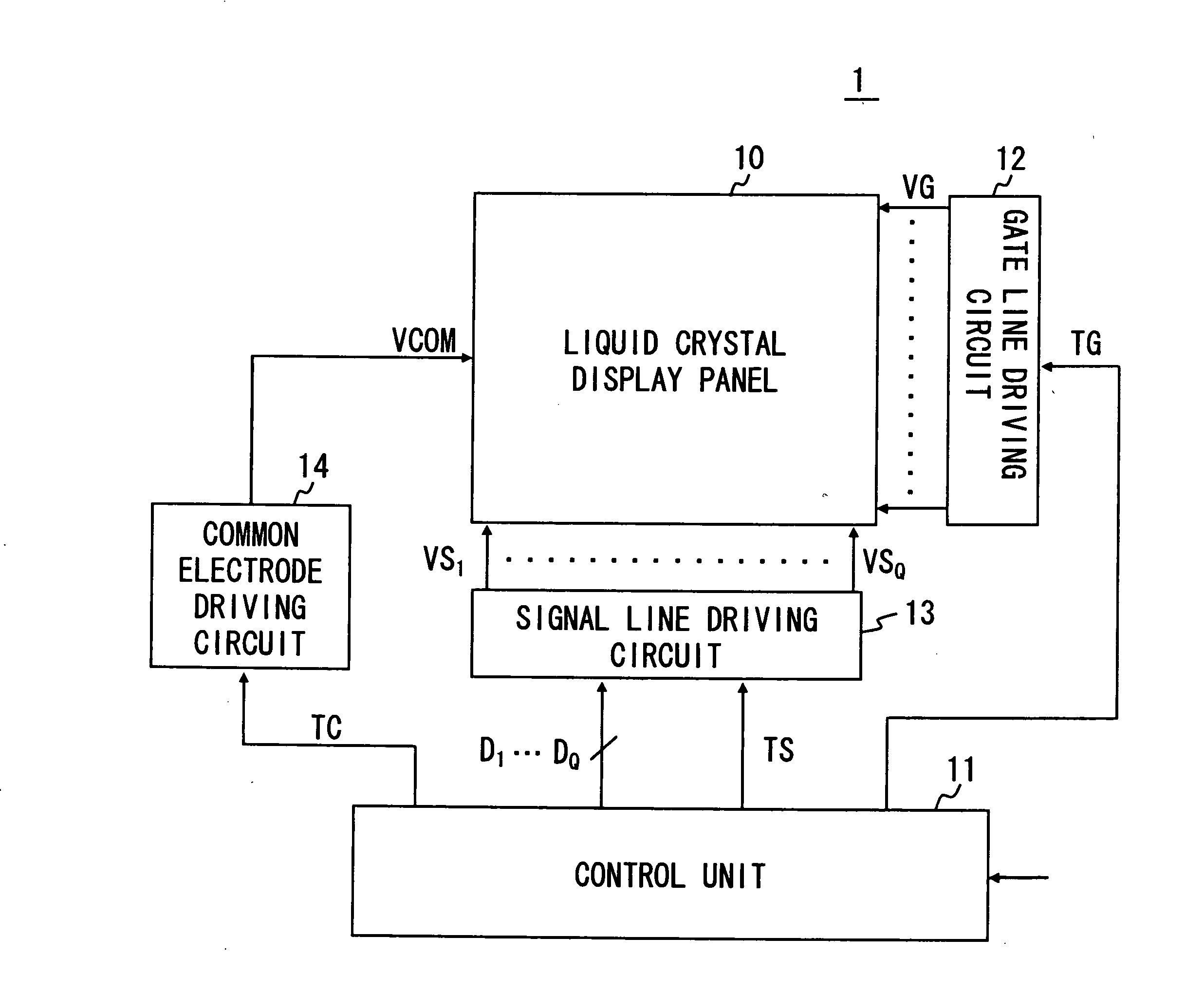
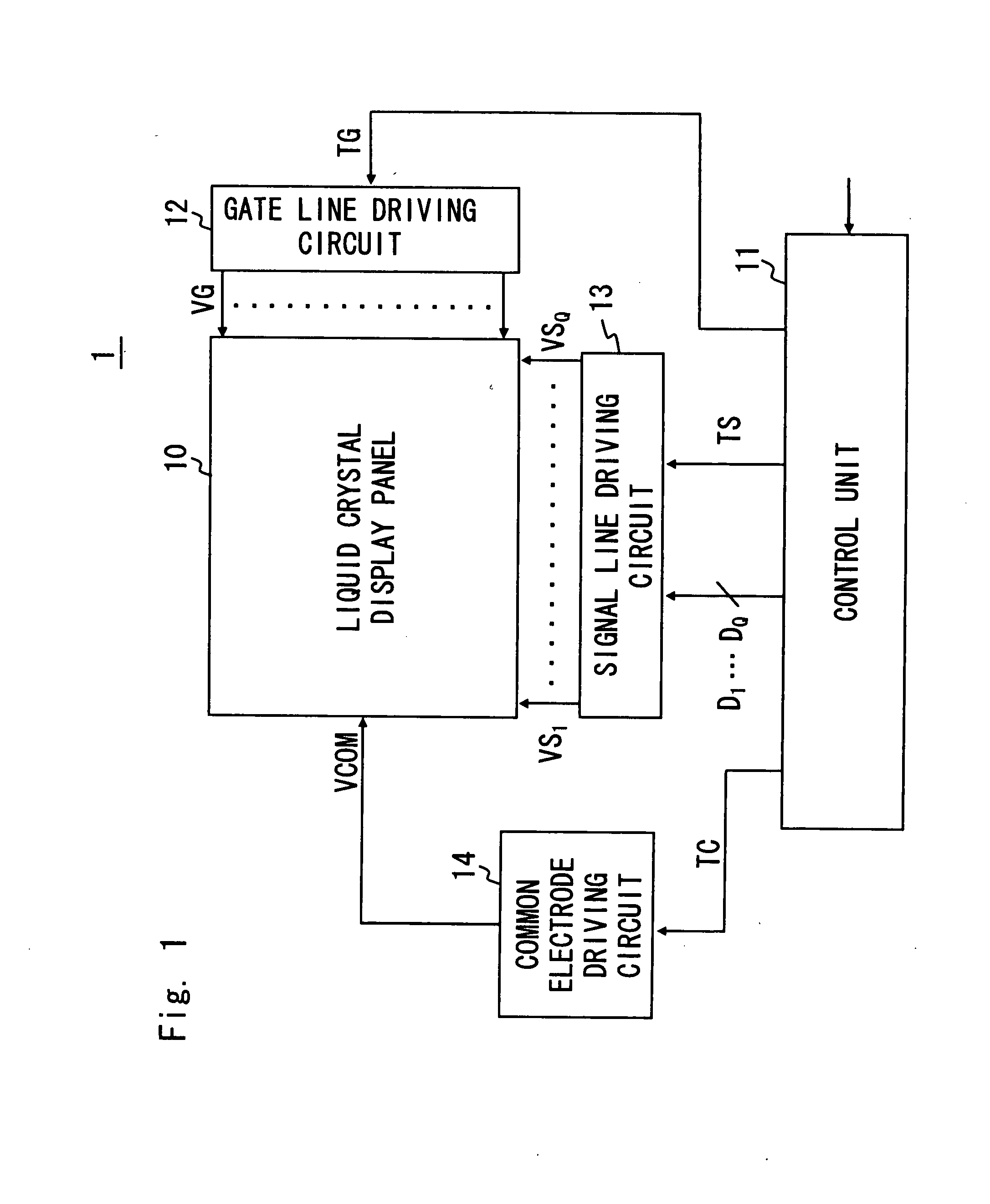
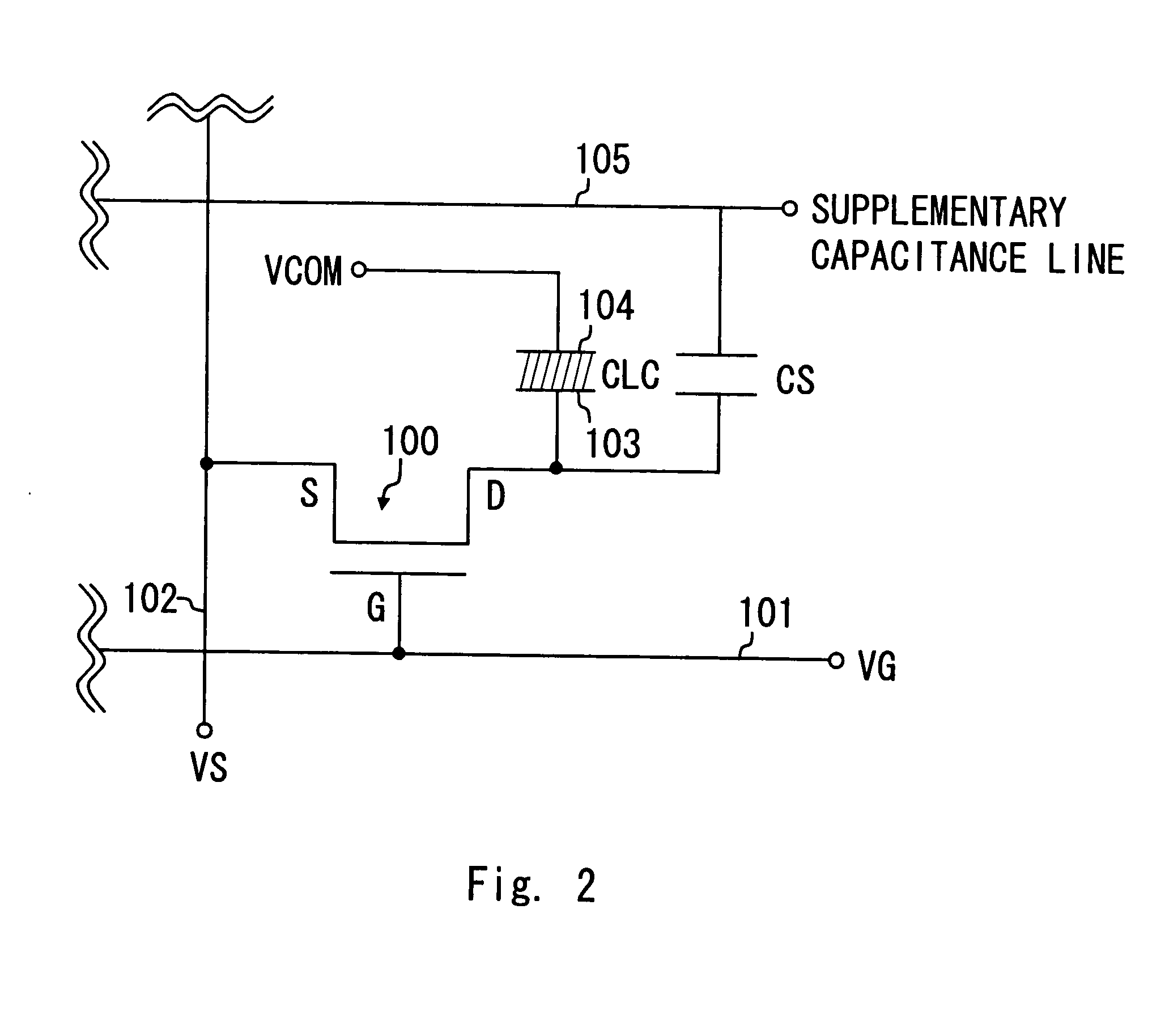
[0044]A schematic configuration of a liquid crystal display apparatus 1 according to this embodiment is shown in FIG. 1. In FIG. 1, a liquid crystal display panel 10 is an active matrix type liquid crystal display panel using TFTs (Thin Film Transistor) for switching devices. The liquid crystal display panel 10 includes TFTs, liquid crystal capacitance CLC and supplementary capacitance CS in intersections of a plurality of gate lines (scanning lines) and source lines (signal lines) arranged in a lattice. FIG. 2 shows an equivalent circuit of the liquid crystal display panel 10.

[0045]As shown in FIG. 2, a gate electrode G of a TFT 100 is connected with a gate line 101, a source electrode S is connected with a source line 102 and a drain electrode D is connected with a pixel electrode 103 of the liquid crystal capacitance CLC and supplementary capacitance CS. The liquid crystal capacitance CLC is a capacitance included in a liquid crystal held between the pixel electrode 103 and a com...


PUM


Abstract

A decoder circuit configured to output an analog voltage signal according to input digital data includes an operational amplifier, first selection circuit and compensation unit. The operational amplifier includes a plurality of input differential pairs and generates an output voltage by interpolating input voltages applied to the plurality of input differential pairs. The first selection circuit selects the input voltages applied to the plurality of input differential pairs from reference voltages according to the digital data. The compensation unit suppresses a fluctuation in a transient variation characteristic of the input voltages applied to the plurality of input differential pairs depending on a selection of the input voltages by the first selection circuit in case at least one voltage level among the reference voltages is changed.

Description

BACKGROUND OF THE INVENTION[0001]1. Field of the Invention[0002]The present invention relates to a decoder circuit used in a driving circuit of a liquid crystal display panel or the like. More particularly, the present invention relates to a decoder circuit that is able to selectively output a voltage from gray-scale voltages corresponding to the number of gray-scale levels in input digital data by generating voltages for interpolating reference voltages smaller in the number of the gray-scale levels.[0003]2. Description of Related Art[0004]A decoder circuit used in a driving circuit of a liquid crystal display panel converts digital image data input externally into an analog signal to supply to a signal line of the liquid crystal display panel. If digital data input to the decoder circuit is 10 bits, for example, such decoder circuit must be able to generate an output signal of 210 (1024) ways of voltage levels.[0005]A decoder circuit in general is configured to select one referenc...

Claims


Application Information

Patent Timeline
Patent Type & Authority Applications(United States)
IPC IPC(8): H03M1/06
CPCG09G3/3688H03M1/68H03M1/0863G09G2310/027G09G3/36H03M1/66G02F1/133G09G3/20
Inventor SHIMATANI, ATSUSHI
Owner RENESAS ELECTRONICS CORP
Why Eureka
Try Eureka