Device and method for material processing by means of laser radiation

a laser radiation and material technology, applied in the direction of laser beam welding apparatus, manufacturing tools, surgery, etc., can solve the problems of reducing affecting the quality of the cut, and the cut would be incomplete, so as to facilitate the recognition of the cut surface, reduce the distance of the center of interaction, and increase the speed of the scanning uni

Inactive Publication Date: 2008-03-13
CARL ZEISS MEDITEC AG
View PDF22 Cites 12 Cited by
  • Summary
  • Abstract
  • Description
  • Claims
  • Application Information

AI Technical Summary

Benefits of technology

[0018]The inventive minimization of the distance between centers of interaction, e.g. of the distance between the focus positions of adjacent optical breakthroughs, according to variant I allows the processing pulse energy to be decreased. The parameter describing the pulse energy is the fluence, i. e. the energy per area or the areal density of energy. Thus, the inventive variant 1 with a distance of less than 10 μm addresses an aspect of the finding attributable for the first time to the inventors.
[0033]This approach is particularly important in generating a partial volume during the fs-LASIK method. This partial volume, also referred to as a lenticule, is generated by a posterior portion and an anterior portion of the cut surface, so that the cut surface as a whole circumscribes the lenticule. However, generating the posterior and anterior portions together within the characteristic time for forming the macrobubbles may result in relatively high demands on the scanning unit's speed of deflection or inevitably leads to special scanning paths. Preferably, this can be avoided by dividing the posterior and anterior portions into partial surfaces and skillfully selecting the processing sequence of these partial surfaces.

Problems solved by technology

However, this process takes very much longer than the forming of the bubble itself.
Visual deficiencies of the eye are often due to the fact that the refractive properties of the cornea and of the lens do not cause optimal focusing on the retina.
The publication explains that the joining of still growing plasma bubbles reduces the quality of the cut.
Otherwise, the material connections would remain and the cut would be incomplete.
This class required operating personnel, for example a physician or a nurse, to wear protective goggles, which naturally makes patients feel uneasy.
If the excessive energy were further increased, unnecessarily large plasma bubbles would be generated and the quality of the cut would deteriorate.
However, producing a cut now no longer stringently requires working with optical breakthroughs.
The individual laser pulse then no longer securely generates an optical breakthrough; the separation of tissue is caused only if the zones of interaction overlap.
However, a fine cut surface can also be a disadvantage, e.g. if a surgeon wants to optically recognize at least part of the cut surface.
In case of a very fine, i.e. smooth cut surface, it may occur that the surgeon can no longer see the profile of the cut surface in the material from outside.
Therefore, he will not know where the periphery of the partial volume lies and will not be able to securely guide the spatula.
However, generating the posterior and anterior portions together within the characteristic time for forming the macrobubbles may result in relatively high demands on the scanning unit's speed of deflection or inevitably leads to special scanning paths.
Practical limits are given by the fact that switching between the anterior and posterior portions always requires shifting of the laser focus along the optical axis, which for technical reasons takes up most of the time during scanning.

Method used


Image

  • Device and method for material processing by means of laser radiation
  • Device and method for material processing by means of laser radiation
  • Device and method for material processing by means of laser radiation

Examples


Embodiment Construction

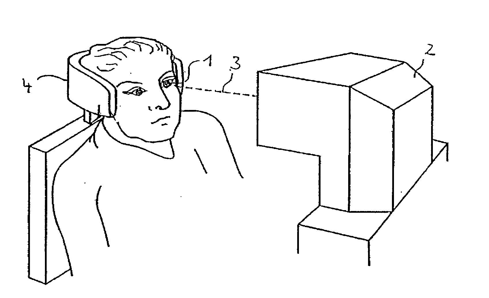
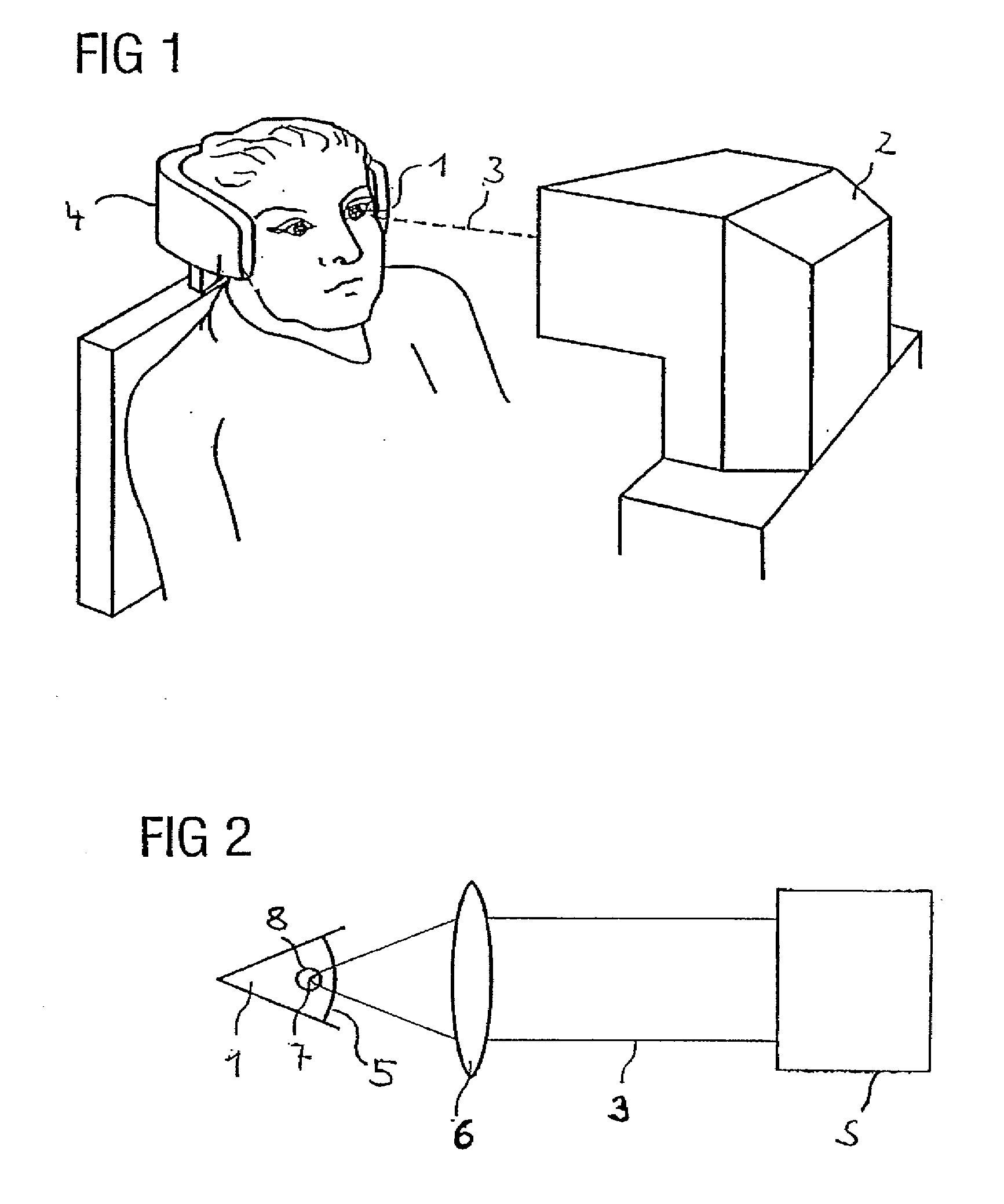
[0051]FIG. 1 shows a laser surgical instrument for treatment of a patient's eye 1, said laser surgical instrument 2 serving to effect a refractive correction. For this purpose, the instrument 2 emits a treatment laser beam 3 onto the eye of the patient 1 whose head is fixed in a head holder 4. The laser surgical instrument 2 is capable of generating a pulsed laser beam 3 such that the method described in U.S. Pat. No. 5,984,916 can be carried out. For example, the treatment laser beam 3 consists of fs-laser pulses having a pulse repetition rate of between 10 and 500 kHz. In the exemplary embodiment, the structural components of the instrument 2 are controlled by an integrated control unit.

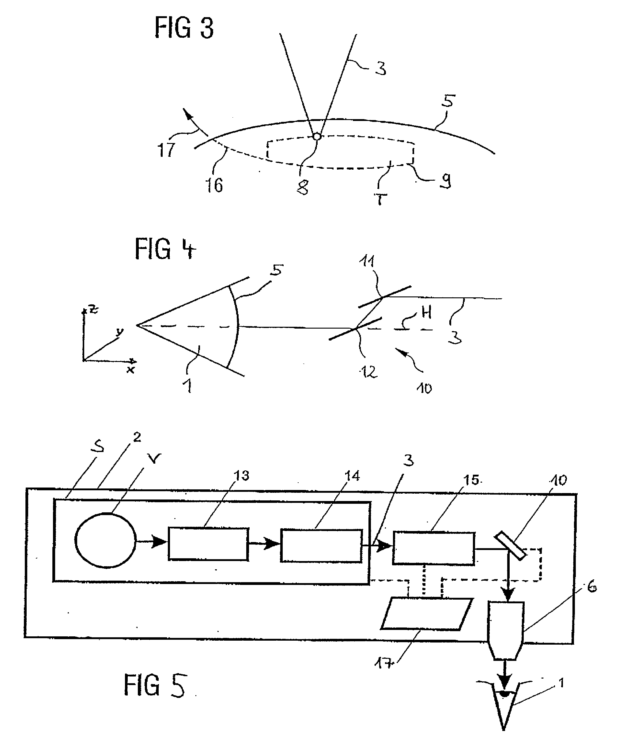
[0052]As schematically shown in FIG. 2, the laser surgical instrument 2 comprises a source of radiation S whose radiation is focused into the cornea 5 of the eye 1. Using the laser surgical instrument 2 a visual deficiency of the patient's eye 1 is corrected by removing material from the cornea 5 s...


PUM

PropertyMeasurementUnit
timeaaaaaaaaaa
spatial distanceaaaaaaaaaa
distanceaaaaaaaaaa

Abstract

A device for material processing by laser radiation, including a source of laser radiation emitting pulsed laser radiation for interaction with the material, optics focusing the pulsed processing laser radiation to a center of interaction in the material, and a scanning unit shifting the positions of the center of interaction within the material. Each processing laser pulse interacting with the material in a zone surrounding the center of interaction assigned to the laser pulse so that material is separated in the zones of interaction. A control unit controls the scanning unit and the source of laser radiation such that a cut surface is produced in the material by sequential arrangement of zones of interaction. The control unit controls the source of laser radiation and the scanning unit such that adjacent centers of interaction are located at a spatial distance a ≦10 μm from each other.

Description

RELATED APPLICATION[0001]The present application claims the benefit of U.S. Provisional Application No. 60 / 726,887, filed Oct. 14, 2005, which is incorporated herein in its entirety by reference.FIELD OF THE INVENTION[0002]The invention relates to a device for material processing by means of laser radiation, said device comprising a source of laser radiation emitting pulsed laser radiation for interaction with the material; optics focusing the pulsed processing laser radiation to a center of interaction in the material; a scanning unit shifting the positions of the center of interaction within the material, wherein each processing laser pulse interacts with the material in a zone surrounding the center of interaction assigned to said laser pulse so that material is separated in the zones of interaction; and a control unit which controls the scanning unit and the source of laser radiation such that a cut surface is produced in the material by sequential arrangement of zones of intera...

Claims


Application Information

Patent Timeline
Patent Type & Authority Applications(United States)
IPC IPC(8): A61B18/20
CPCA61F9/00827A61F2009/00872A61F2009/00897B23K26/026B23K26/0876B23K26/02B23K26/0635B23K26/035B23K26/0624
Inventor BISCHOFF, MARKMUHLHOFF, DIRKSTOBRAWA, GREGOR
Owner CARL ZEISS MEDITEC AG
Why Eureka
Try Eureka