Variable valve timing controller for internal combustion engine
a timing controller and internal combustion engine technology, applied in the direction of valve drives, electric control, instruments, etc., can solve the problem of reducing the supply voltag
- Summary
- Abstract
- Description
- Claims
- Application Information
AI Technical Summary
Benefits of technology
Problems solved by technology
Method used
Image
Examples
Embodiment Construction
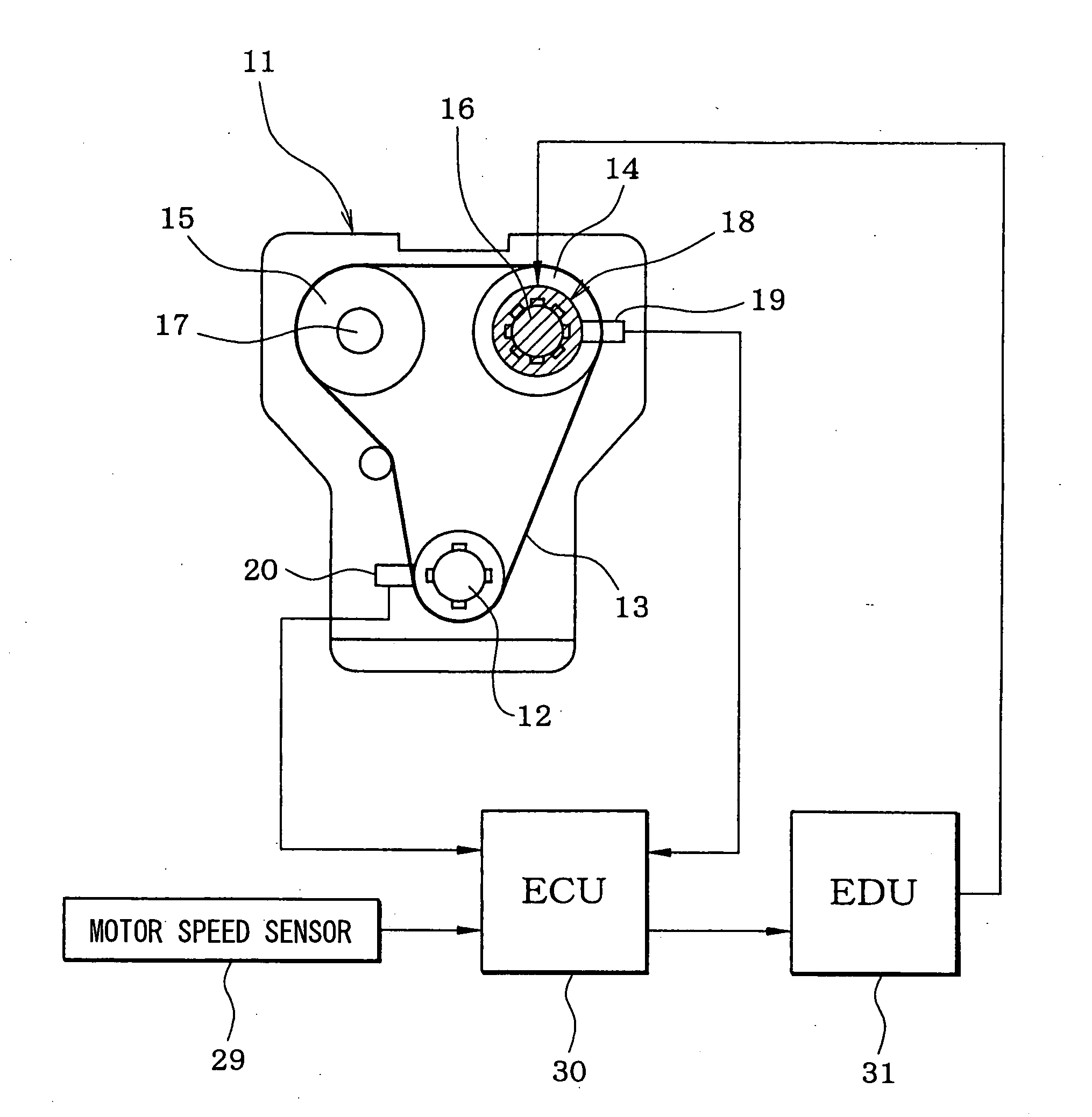
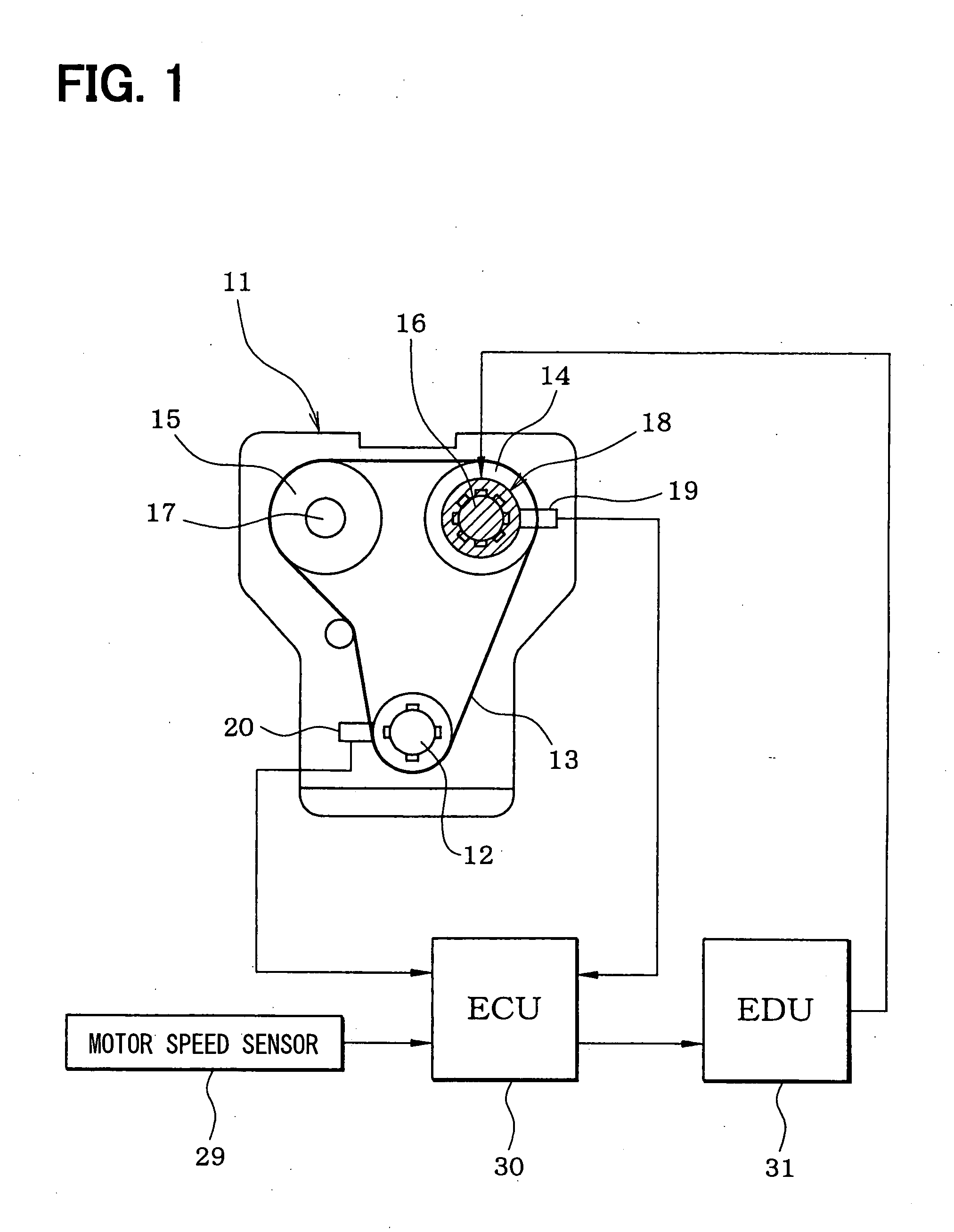
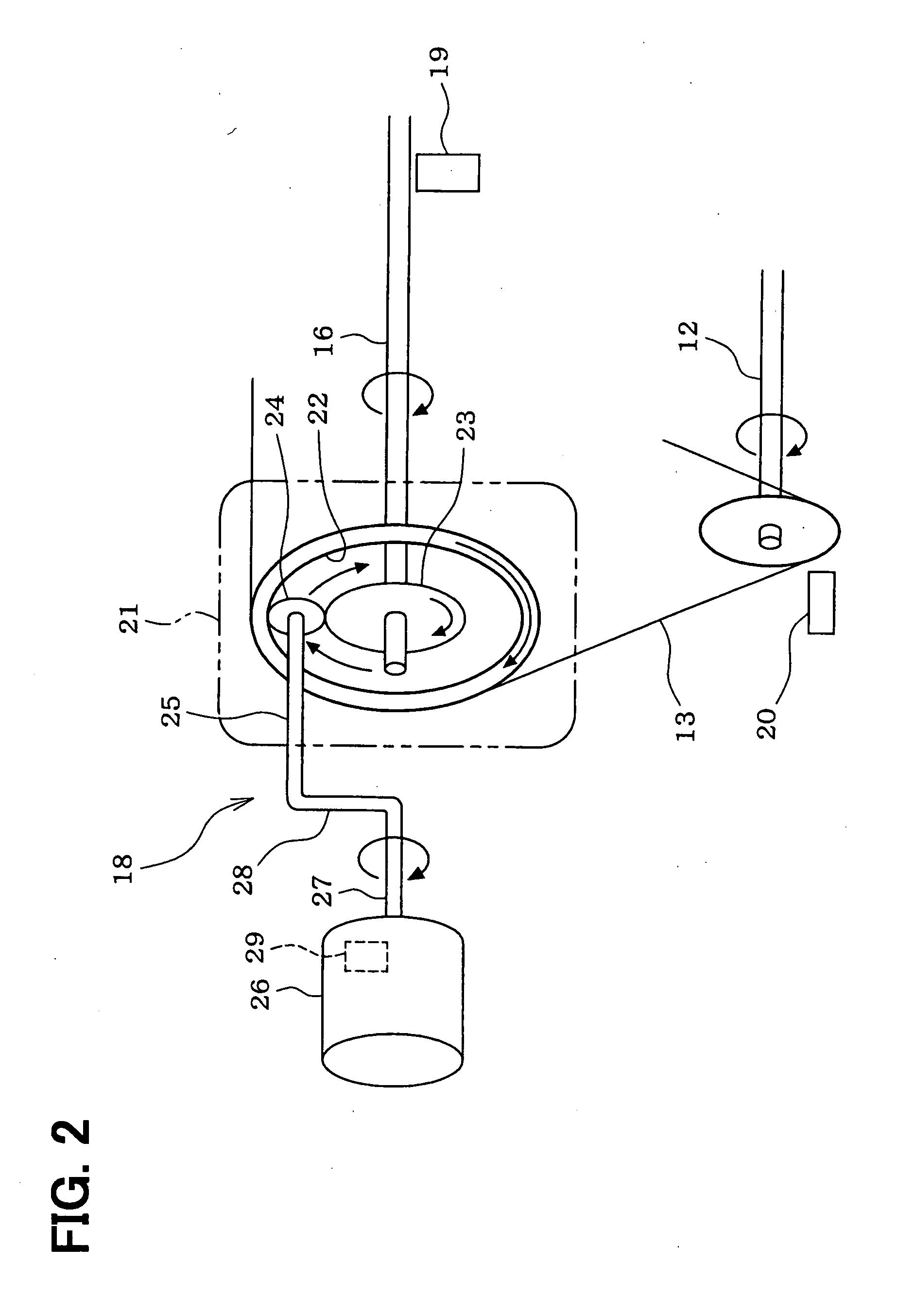
[0015] An embodiment of the present invention will be described hereinafter. FIG. 1 schematically shows a whole structure of an engine control system. An internal combustion engine 11, which is referred to as an engine hereinafter, includes a crankshaft 12. A driving force of the crankshaft 12 is transmitted to an intake camshaft 16 and an exhaust camshaft 17 through a timing chain 13 (or a timing belt) and sprockets 14, 15. A variable valve timing controller 18, which includes an electric motor, is coupled to the intake cam shaft 16. The variable valve timing controller 18 varies a rotational phase (camshaft phase) of the intake camshaft 16 relative to the crankshaft 12 so that the valve timing of an intake valve (not shown) is adjusted.
[0016] A cam angle sensor 19 is provided around the intake camshaft 16. The cam angle sensor 19 outputs a cam angle signal every predetermined cam angle of the intake camshaft 16. A crank angle sensor 20 is provided around the cranks shaft 12. The ...
PUM
 Abstract
Description
Claims
Application Information
 - R&D
- Intellectual Property
- Life Sciences
- Materials
- Tech Scout
- Unparalleled Data Quality
- Higher Quality Content
- 60% Fewer Hallucinations
Browse by: Latest US Patents, China's latest patents, Technical Efficacy Thesaurus, Application Domain, Technology Topic, Popular Technical Reports.
© 2025 PatSnap. All rights reserved.Legal|Privacy policy|Modern Slavery Act Transparency Statement|Sitemap|About US| Contact US: help@patsnap.com


