
Magnetostrictive coat forming method, magnetostrictive torque sensor manufacturing method, and electric power steering apparatus employing the sensor

a magnetostrictive torque and sensor technology, applied in the direction of magnets, magnet bodies, instruments, etc., can solve the problems of unavoidably deteriorating detection accuracy, long heating time of steering shafts, and large hysteria, so as to stable torque detection, and avoid undesired fluctuation in detected steering torque output

Active Publication Date: 2008-03-20
HONDA MOTOR CO LTD
View PDF7 Cites 8 Cited by
  • Summary
  • Abstract
  • Description
  • Claims
  • Application Information

AI Technical Summary

Benefits of technology

The solution enhances torque detecting accuracy, reduces hysteresis, and maintains consistent sensitivity, providing improved steering feel and reliability even in high-temperature environments, allowing for precise control of the steering system.

Problems solved by technology

However, in the case where an annular magnetostrictive coat is formed on the rotational shaft by first wrapping a masking tape on part of the surface of the rotational shaft to thereby mask the surface and then plating the masked surface as taught in the No. 3268089 patent publication, the magnetostrictive coat would have a greater thickness at its opposite axial end portions than the remaining coat portion, which would unavoidably deteriorate the detection accuracy due to reasons to be described later.
However, the above-discussed conventional magnetostrictive torque sensor 102 has several drawbacks, such as instable detected values of the steering torque, great hysteresis, a considerably long time for heating the steering shaft (mag netostrictive coats) and poor productivity. FIG. 44 is a graph showing an example of actual reverse magnetostrictive characteristics of the conventional magnetostrictive torque sensor 102, where the horizontal axis represents the input steering torque while the vertical axis represents the impedance or induced voltage detected by the detecting coils when an A.C. voltage has been supplied to the exciting coil.
Therefore, in the case where such a magnetostrictive torque sensor is employed in an electric power steering apparatus, the magnetostrictive torque sensor would deteriorate a steering feel and thus can not be suitably put to practical use.
Further, the conventional magnetostrictive torque sensor suffers from another problem that the reverse magnetostrictive characteristics are susceptible to influences of characteristics of the magnetostrictive coat formed by the plating performed prior to the heating process, as shown in FIGS. 45A-45D comparatively illustrating measurements of the reverse magnetostrictive characteristics before and after the heating process.
Further, the magnetostrictive torque sensor, made by the above-discussed conventional manufacturing method, has the problem that its zero torque point and sensitivity would vary if it has been exposed for a long time in an engine room heated to a high temperature in the order of 80-100° C. FIG. 46 is a diagram showing high-temperature durability characteristics of the magnetostrictive torque sensor made by the above-discussed conventional manufacturing method.
Such changes are due to a creep of the plating (which would remove distortion from the plating), and the characteristics at the beginning of the use can not be restored because the characteristics after occurrence of the creep are retained even after the cooling.
Because the sensitivity of the torque sensor is generally set, during manufacture of the torque sensor, so as to achieve an optimal control amount of the torque, variation from the thus-set sensitivity may often lead to an uncomfortable steering feel.

Method used


Image

  • Magnetostrictive coat forming method, magnetostrictive torque sensor manufacturing method, and electric power steering apparatus employing the sensor
  • Magnetostrictive coat forming method, magnetostrictive torque sensor manufacturing method, and electric power steering apparatus employing the sensor
  • Magnetostrictive coat forming method, magnetostrictive torque sensor manufacturing method, and electric power steering apparatus employing the sensor

Examples


first embodiment

[0089] First, a description will be given about a magnetostrictive-coat forming method in accordance with the present invention.

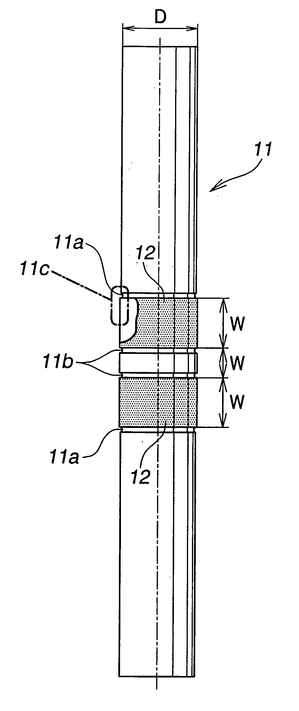
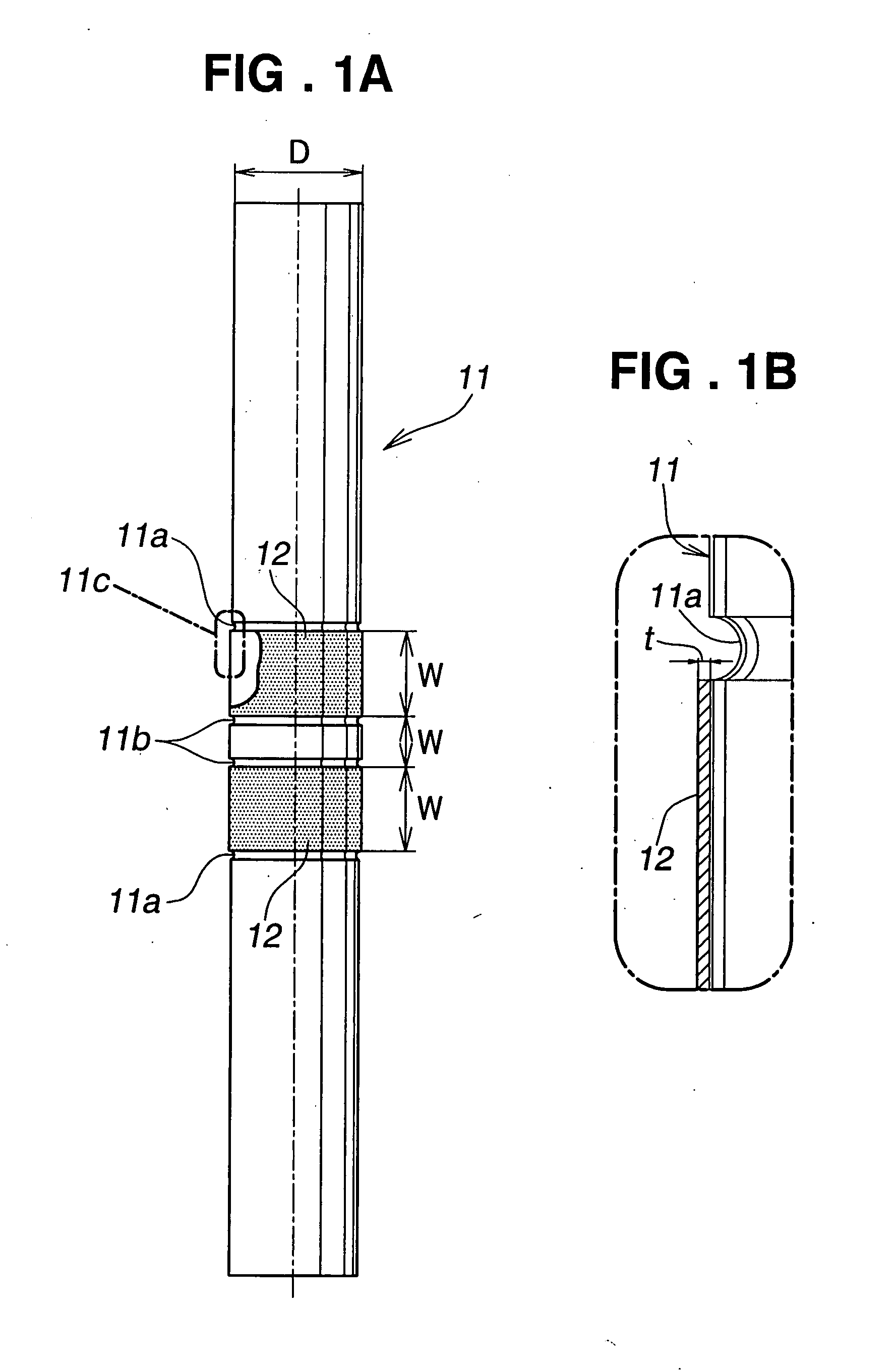
[0090]FIG. 1A is a view illustrating a steering shaft having magnetostrictive coats formed thereon, and FIG. 1B is an enlarged view of a section depicted by reference character 11C in FIG. 1B. As seen in FIGS. 1A and 1B, two annular magnetostrictive coats 12, for example, in the form of Ni—Fe plating, are formed, at a predetermined interval, on the outer circumferential surface of the steering shaft 11 of an electric power steering apparatus. Annular grooves 11a or 11b are formed in and along the outer circumferential surface of the shaft 11 near axial opposite ends of each of the two magnetostrictive coats 12. In the illustrated example, the steering shaft 11 has a diameter D of 20 mm, each of the magnetostrictive coats 12 has a width (axial dimension) of 14 mm, the interval w between the magnetostrictive coats 12 is 8 mm, and a target thickness of each of...

second embodiment

[0111] Next, a description will be given about the magnetostrictive torque sensor manufactured by the method of the present invention and the electric power steering apparatus equipped with such a magnetostrictive torque sensor, as the present invention.

[0112]FIG. 14 is a view, similar to FIG. 40, which shows the magnetostrictive torque sensor manufactured by the method of the present invention and the electric power steering apparatus equipped with the magnetostrictive torque sensor. The electric power steering apparatus 30 shown in FIG. 14 is generally similar to the electric power steering apparatus 100 of FIG. 40 except for the manufacturing method of the magnetostrictive torque sensor 31, and thus the same components as those in FIG. 40 are represented by the same reference characters and will not be described here to avoid unnecessary duplication.

[0113] In the illustrated example of FIG. 14, the steering shaft (rotational shaft) 109b, connected to the steering wheel 101, is r...

third embodiment

[0142]FIG. 30 is a view, similar to FIG. 40, which shows the magnetostrictive torque sensor manufactured by the manufacturing method of the present invention and the electric power steering apparatus equipped with the magnetostrictive torque sensor. The electric power steering apparatus 40 shown in FIG. 30 is generally similar to the electric power steering apparatus 100 of FIG. 40 except for the manufacturing method of the magnetostrictive torque sensor 41, and thus the same components as those in FIG. 40 are represented by the same reference characters and will not be described here to avoid unnecessary duplication.

[0143] The steering torque detector section 41 employed in the electric power steering apparatus 40 includes the magnetostrictive torque sensor having magnetostrictive coats which are provided on upper and lower portions (42 and 43) of the outer circumferential surface of the steering shaft (rotational shaft) 109b by plating the upper end lower portions, for example, wi...


PUM

PropertyMeasurementUnit
temperatureaaaaaaaaaa
thicknessaaaaaaaaaa
temperatureaaaaaaaaaa

Abstract

For forming an annular magnetostrictive coat on an outer peripheral surface of a rotational shaft associated with a magnetostrictive torque sensor, a magnetostrictive-coat forming method comprises a step of fitting a cylindrical masking jig over the outer peripheral surface of the rotational shaft and securing the masking jig to the outer peripheral surface, a step of placing the rotational shaft in a plating tank to thereby form the magnetostrictive coat by plating on the outer peripheral surface, and a step of detaching the masking jig from the rotational shaft.

Description

CROSS-REFERENCE TO RELATED APPLICATIONS [0001] This application is a Division of application Ser. No. 10 / 844,824, filed May 12, 2004, which application is incorporated herein by reference.FIELD OF THE INVENTION [0002] The present invention relates generally to a magnetostrictive torque sensor and, more particularly, to a magnetostrictive torque sensor for detecting a steering torque in an electric power steering apparatus for motor vehicles. BACKGROUND OF THE INVENTION [0003] As well known, the electric power steering apparatus are steering assisting apparatus which are designed to drive an electric motor as a human operator or driver manually operates a steering wheel, during driving of a motor vehicle, to thereby assist the driver's manual steering effort. In such electric power steering apparatus, the steering assisting motor, which provides a steering torque assist (or steering assist torque), is driven by a motor control device in accordance with a PWM (Pulse Width Modulation) ...

Claims


Application Information

Patent Timeline
Patent Type & Authority Applications(United States)
IPC IPC(8): H01F7/02B62D5/04G01L3/10
CPCG01L3/102G01L3/103Y10T29/4902Y10T29/49078Y10T29/49224Y10T29/49002Y10T29/49005
Inventor SHIMIZU, YASUONAKAMURA, YOSHITOSUEYOSHI, SHUNICHIROYOSHIMOTO, NOBUHIKOKOBAYASHIFUKUDA, YUICHIDOI, MIZUHOHARADA, HITOSHIHOSHI, TOMOHIRO
Owner HONDA MOTOR CO LTD
Learn More