Depressurization Type Drying Machine and Method for Drying Lumber Using the Same

a drying machine and pressurization technology, which is applied in drying machines, lighting and heating apparatus, furniture, etc., can solve the problems of short apparatus practicability, energy-saving properties and productivity, and irregular drying of lumber surface, etc., to achieve excellent reliability, improve efficiency, and improve efficiency

Inactive Publication Date: 2008-03-20
KAKUNO SEISAKUSHO
View PDF98 Cites 28 Cited by
  • Summary
  • Abstract
  • Description
  • Claims
  • Application Information

AI Technical Summary

Benefits of technology

[0120] As described above, according to a depressurization type drying machine of the invention, the following advantageous effects may be brought about.
[0121] The following effects may be brought about by the first aspect of the invention.
[0122] (1) Since the ceiling portion, sidewall portions, and floor portion of the drying chamber are formed to be a dual-structure composed of the outer wall and inner wall, and the system is provided with a sealing type door disposed at the front sidewall portion of the drying chamber and a heat insulation layer formed between the outer wall and the inner wall, the system may increase the efficiency when cooling and heating the interior of the drying chamber by controlling heat radiation from the drying chamber and heat absorption from the exterior of the drying chamber. Therefore, it is possible to provide a depressurization type drying machine having an excellent energy-saving properties and excellent reliability, by which the temperature in the drying chamber is stably maintained at a low temperature.
[0123] (2) Since the ceiling portion and sidewall portions are formed roughly like a circular arc swelled outwardly, it is possible to provide a depressurization type drying machine, having excellent durability, in which the ceiling portion and sidewall portions are only resiliently deformed even by depressurizing the interior of the drying chamber, wherein no plastic deformation occurs, and even if depressurization is repeated, the drying chamber is not broken.
[0124] (3) Since reinforcement ribs are provided, which are disposed along the outer circumference of the inner wall parallel to and / or in orthogonal to the lengthwise direction of the drying chamber between the respective outer walls and inner walls of the ceiling portion, the sidewall portions, and the floor portion, it is possible to provide a depressurization type drying machine, having excellent productivity, in which the outer walls and inner walls are firmly supported by means of the reinforcement ribs, wherein since the ceiling portion and the sidewall portions may be securely prevented from being deformed, the interior of the drying chamber may be depressurized at a high pressure, and the material may be uniformly dried in a short time.
[0125] (4) Since the ceiling portion and the sidewall portions of the drying chamber are formed to be roughly like a circular arc swelled outwardly, it is possible to provide a depressurization type drying machine, having an excellent treatment capacity, in which rectification of air may be made favorable in the interior of the drying chamber, and the capacity of the drying chamber may be increased.

Problems solved by technology

However, there are the following problems in the prior arts described above.
(1) In (Patent Document 1), since the reduction pressure is remarkably slight although drying is carried out by repeating dehumidification and depressurization, only the surface of lumber is first dried, drying irregularities are apt to occur at the surface of lumber and in the core portion thereof, and it takes a long time until the core portion is dried.
Therefore, the apparatus according to Patent Document 1 has problems in that the apparatus is short in practicability, energy-saving properties and productivity, and the surface of lumber is apt to be cracked, wherein reliability is not sufficient.
Also, since the drying chamber thereof is not provided with any air path, it is difficult to uniformly dry lumber, wherein there is another problem that since the lumber is apt to be warped, cracked, or is subjected to bending and contraction, reliability is not sufficient.
Further, there is still another problem that since the atmospheric air is taken in the drying chamber during drying, it is difficult to uniformly control the temperature and humidity, and the apparatus is short in practicability and operation efficiency.
(2) In (Patent Document 2), since heating is carried out by a far-infrared ray heater, the facility cost and running cost are expensive, cost performance is not satisfactory, and at the same time, since an air path is formed only on the upper surface of the drying apparatus, it is not possible to send air from the upper surface or from the sides in the lengthwise direction to lumber, wherein since air is supplied only from one end (the front side) in the lengthwise direction, uniformly drying cannot be carried out and cracking is apt to occur at the end face portions, wherein there is a problem that the apparatus is short in reliability.
Further, since the atmospheric air is taken in during drying, it is difficult to uniformly control the temperature and humidity, wherein there is another problem that the apparatus is short in practicability and operation efficiency.

Method used


Image

  • Depressurization Type Drying Machine and Method for Drying Lumber Using the Same
  • Depressurization Type Drying Machine and Method for Drying Lumber Using the Same
  • Depressurization Type Drying Machine and Method for Drying Lumber Using the Same

Examples


embodiment 1

[0239] A description is given below of a depressurization type drying machine according to Embodiment 1 of the invention with reference to the accompanying drawings.

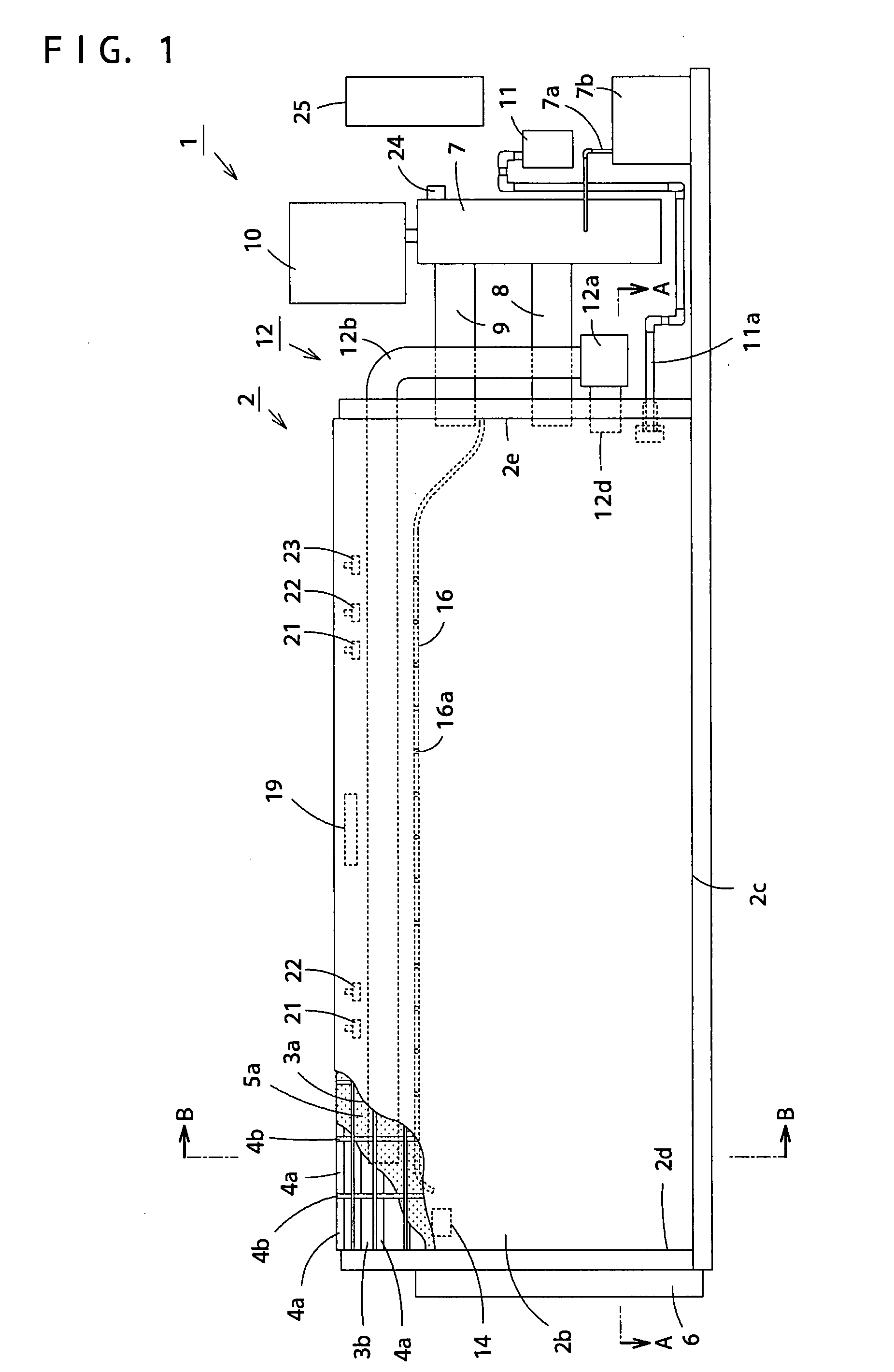
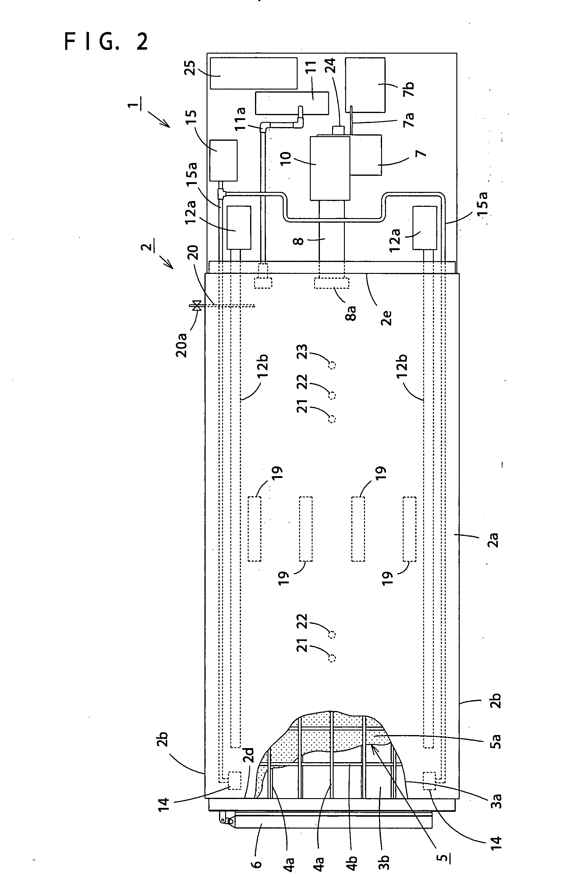
[0240]FIG. 1 is a partially broken perspective side view showing the major parts of a depressurization type drying machine according to Embodiment 1 of the invention, FIG. 2 is a partially broken perspective plan view showing the major parts of Embodiment 1 of the invention, FIG. 3 is a sectional plan view taken along the line A-A of FIG. 1, and FIG. 4 is a sectional front view taken along the line B-B of FIG. 1.

[0241] In FIG. 1 through FIG. 4, reference numeral 1 denotes a depressurization type drying machine according to Embodiment 1 of the invention. Reference numeral 2 denotes a drying chamber in which the ceiling portion 2a, sidewall portions 2b and floor portion 2c shown in FIG. 4 are formed to be a dual structure consisting of the outer wall 3a and the inner wall 3b. Reference numerals 4a and 4b denote lattice r...

embodiment 2

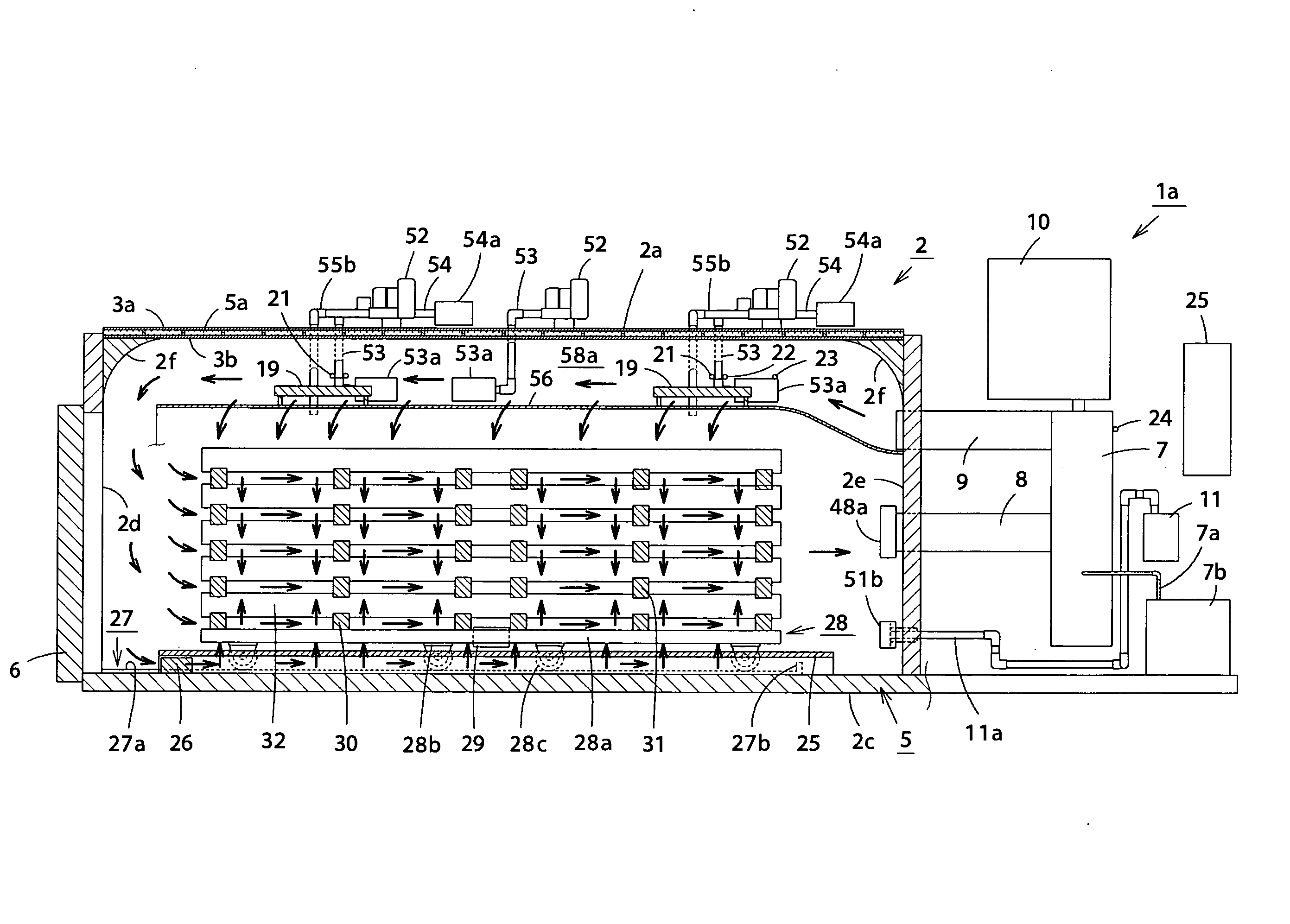
[0312]FIG. 9 is a sectional front view of the major parts, showing a drying state of lumber in a depressurization type drying machine according to Embodiment 2, and FIG. 10 is a sectional view side taken along the line E-E of FIG. 9. Components that are identical to those of Embodiment 1 are given the same reference numerals, and description thereof is omitted.

[0313] In FIG. 9 and FIG. 10, reference numeral 1a denotes a depressurization drying machine according to Embodiment 2 of the invention. Reference numeral 48a denotes an air filter disposed at the tip end at the inner part side of the drying chamber 2 of the suction duct 8, 51b denotes an air filter disposed at the tip end at the inner part side of the drying chamber 2 of the depressurization pipe 11a, 52 denotes a blower that is disposed at the ceiling portion 2a of the drying chamber 2 and circulates air in the interior of the drying chamber 2, 53 denotes an inlet pipe, to which the air filter 53a is attached, for taking dr...


PUM


Abstract

The present invention provides a depressurization type drying machine that is capable of repeatedly reducing the pressure, heating and humidifying during drying, uniformly drying a material to be dried, in a short time by applying vibrations to the material to be dried when reducing the pressure, and reducing consumption power without damaging the material to be dried, is excellent in reliability, productivity and energy-saving properties, brings about almost no flaws such as warping, internal cracking, breaking, shrinkage, bending, and surface cracking, especially when drying lumber, is also capable of leaving gloss on the surface of lumber after drying and scent without any discoloring, has high commercial value since the humidity in a building may be permanently controlled in response to the environment after being constructed, and is capable of extracting moisture contained in a material to be dried such as lumber without any waste and effectively utilizing the same as by-products. At least the ceiling portion and sidewall portions are formed roughly like a circular arc swelled outwardly, and reinforcement ribs are provided, which are disposed along the outer circumference of the inner wall parallel to and / or in orthogonal to the lengthwise direction of the drying chamber between the respective outer walls and inner walls of the ceiling portion, the sidewall portions and the floor portion.

Description

TECHNICAL FIELD [0001] The present invention relates to a depressurization type drying machine and a method for drying lumber using the same, which are capable of uniformly drying organisms such as lumber, etc., in a short time by depressurizing, heating, humidifying, dehumidifying the organisms during drying, and simultaneously vibrating materials to be dried when depressurizing. BACKGROUND OF THE INVENTION [0002] Conventionally, first, there is a hot air drying system as a method for artificially drying lumber. In a drying chamber of the system, steam is applied to lumber to be dried and hot air is blown thereinto for drying. Application of steam prevents the lumber from being cracked due to the surface thereof becoming hot by blowing of hot air and transmits heat of hot air into the inside of the lumber by steam. Therefore, in the system, the temperature and humidity in the drying chamber greatly change due to the elapse of time, wherein since the temperature and humidity of lumb...

Claims


Application Information

Patent Timeline
Patent Type & Authority Applications(United States)
IPC IPC(8): F26B5/04
CPCF26B5/04F26B2210/16F26B21/06F26B7/00
Inventor KAKUNO, TOSHIMITSU
Owner KAKUNO SEISAKUSHO
Why Eureka
Try Eureka