Biomass pellet fuel heating device, system and method

a technology of biomass pellets and heating devices, applied in the direction of household stoves or ranges, solid heating fuels, lighting and heating apparatus, etc., can solve the problems of significant burnback risk, ineffective heating, and inefficiency of current pellet delivery methods, so as to achieve dramatic increases in thermal efficiency and reduce the effect of particulate emissions

Inactive Publication Date: 2008-03-20
JOHNSON GEOFFREY W A
View PDF32 Cites 9 Cited by
  • Summary
  • Abstract
  • Description
  • Claims
  • Application Information

AI Technical Summary

Benefits of technology

[0011]The present invention provides a pellet fuel heating device and system and method in which pellet fuel is combusted in a close mode, that

Problems solved by technology

The efficiencies and environmentally-friendly features of current pellet fuel heating devices drive their rising popularity, but drawbacks and inefficiencies remain.
Particulate matter is a primary component of smog and atmospheric pollution, and therefore its generation and release into the atmosphere is an environmental negative.
All of the current pellet delivery methods present a significant burnback risk.
Burnback is a serious and dangerous phenomenon in which the pellets within the hopper are ignited.
Burnback can occur when there is a sufficient trail of fuel between the combustion chamber and the hopper to bridge the two areas.
Such a fuel continuum can occur when the delivery pathway between the hopper and the combustion chamber is clogged with fuel, or fuel build-up.
Some current pellet fuel heating devices use just a nat

Method used


Image

  • Biomass pellet fuel heating device, system and method
  • Biomass pellet fuel heating device, system and method
  • Biomass pellet fuel heating device, system and method

Examples


Embodiment Construction

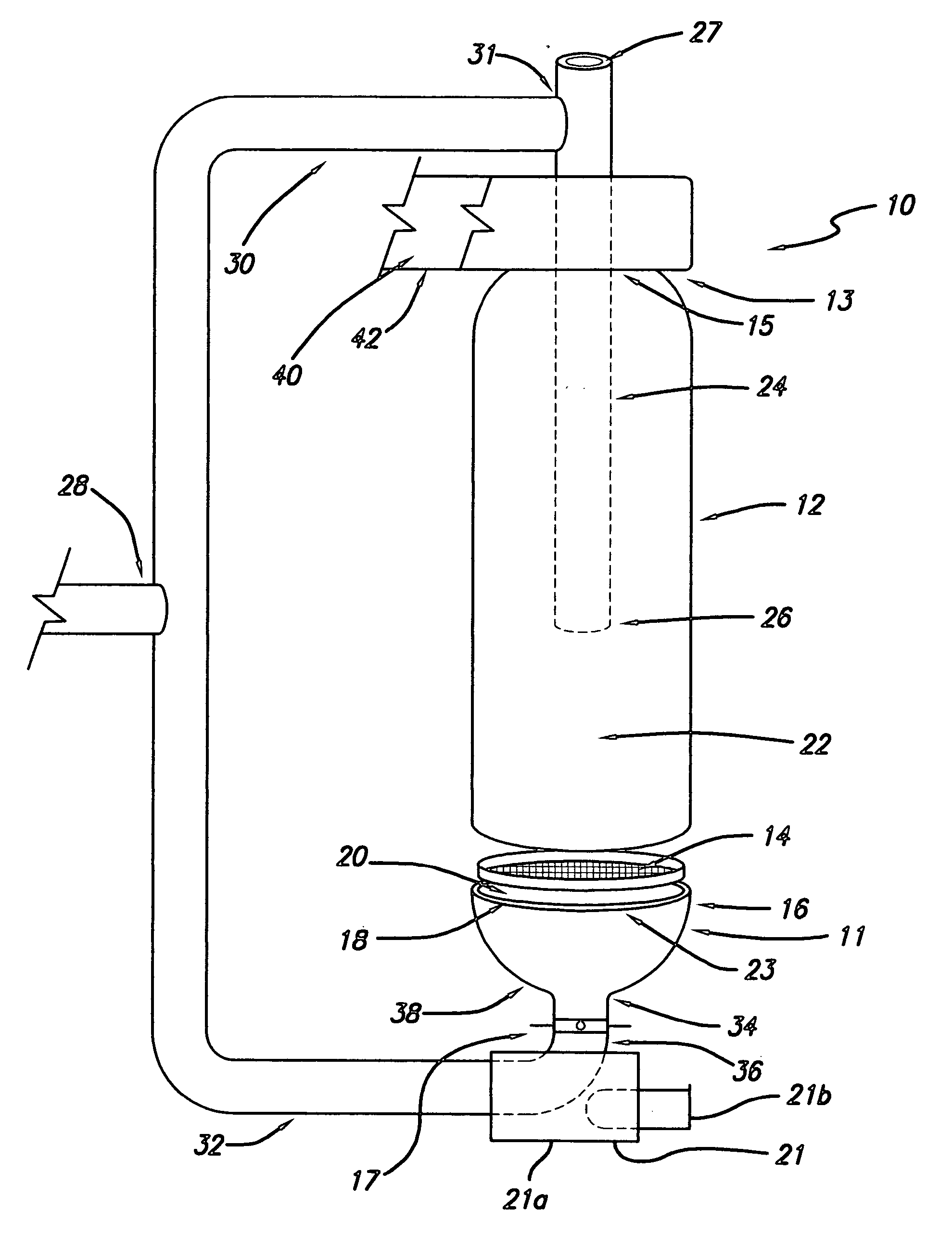
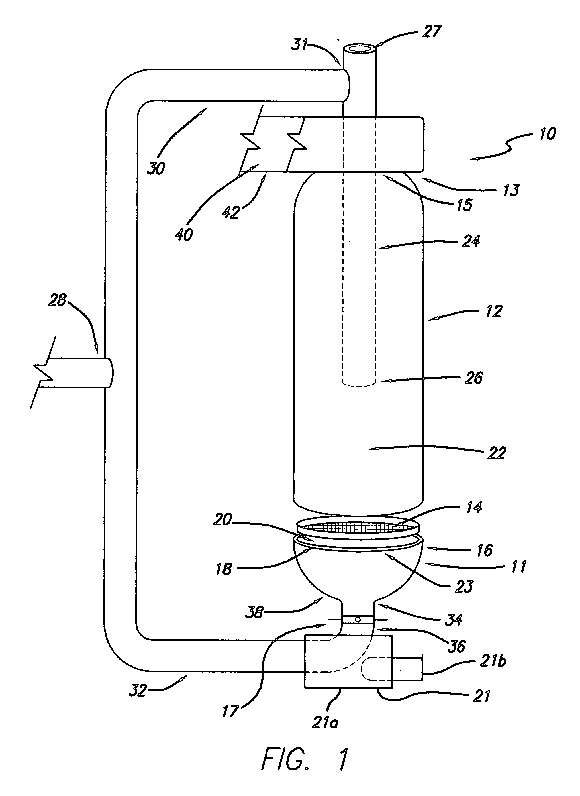
[0020]Referring to FIG. 1 there is shown a pellet fuel heating device, which for simplicity is generally referred to herein as a pellet stove, designated generally by the reference numeral 10. The pellet stove 10 as shown includes a burn pot 11 and a tubular chamber housing 12. The burn pot 11 includes a flat grate 14 and a pot member 16. As shown, and in preferred embodiment, the pot member 16 is an open-topped cylindrical receptacle with a surround or rim 18 encircling an open, upwardly facing, mouth 20.

[0021]The grate 14 is shown in FIG. 1 elevated above the pot member 16 for illustration purposes. In use the grate 14 is seated in the pot member 16 as described in more detail below. The chamber housing 12 is shown in FIG. 1 spaced apart from the pot member 16 for illustration purposes only. In use the chamber housing 12 is mated with the pot member 16. The chamber housing 12 and pot member 16, in combination, form, determine and / or enclose a burn or combustion chamber 22.

[0022]As...


PUM


Abstract

There is provided a pelletized-biomass combustion device comprising: (a) an elongate upright combustion capsule; (b) a grate element disposed within and bisecting the combustion capsule, (i) the grate element having a first side and a second side and (ii) the grate element open to fluid communication between the first side and the second side; (c) a first combustion air inlet facing the first side of the grate; (d) a second combustion air inlet facing the second side of the grate; (e) a fuel-feed inlet; and (f) a flue-gas exhaust outlet. The combustion capsule can be formed of two mated components such as a chamber housing mated with a burn pot member, or instead it can be formed as a single unit such as the chamber housing bisected by the grate. In any event, the grate element has two sides, and there are two combustion air inlets, each facing opposite sides of the grate. The combustion device is preferably an induced-draft system wherein the exhaust fan is positioned at the distal end of the stove pipe.

Description

BACKGROUND OF THE INVENTION[0001]The present invention relates to biomass pellet fuel heating devices, some of which are at times called pellet burners, pellet burning stoves or pellet stoves, and related systems and methods.[0002]Pellet fuel heating devices are used in the USA and other countries. These heating devices, which include without limitation stoves, boilers and furnaces, burn pelletized wood and / or biomass fuels to produce heat. In comparison to natural-form wood burning devices, pellet burners generally have lower emission levels and higher combustion efficiencies. Pelletized fuel is also cleaner and easier to handle than natural-form wood, and is often derived from agricultural and industrial waste materials, including the waste of the timber industry.[0003]The efficiencies and environmentally-friendly features of current pellet fuel heating devices drive their rising popularity, but drawbacks and inefficiencies remain.[0004]The combustion of pellet fuels still produce...

Claims


Application Information

Patent Timeline
IPC IPC(8): F24B13/04
CPCF23B60/02F23B50/12
Inventor JOHNSON, GEOFFREY W.A.
Owner JOHNSON GEOFFREY W A
Why Eureka
Try Eureka