
Monomers and polymers for optical elements

a technology applied in the field of monomers and polymers for optical elements, can solve the problems of complex commercialization of such lenses, only able to correct relatively simple optical distortions, and fabricating techniques that are only capable of achieving relatively simple optical distortion corrections, and achieve the effect of inhibiting the polymerization of the monomer mixtur

Active Publication Date: 2008-03-20
ESSILOR INT CIE GEN DOPTIQUE
View PDF10 Cites 24 Cited by
  • Summary
  • Abstract
  • Description
  • Claims
  • Application Information

AI Technical Summary

Benefits of technology

The patent describes a composition and method for making a polymerizable composition that includes a matrix polymer and a monomer mixture. The monomer mixture includes a thiol monomer and a second monomer selected from ene monomers and yne monomers. The composition can be used to make optical elements with improved refractive index stability. The technical effects of this patent include improved refractive index stability, improved optical element manufacturing efficiency, and reduced polymerization inhibitor usage.

Problems solved by technology

However, lenses made using these materials and fabrication techniques are only capable of correcting relatively simple optical distortions.
However, the commercialization of such lenses has been complicated by the relatively small number of suitable polymer compositions currently available.

Method used


Image

  • Monomers and polymers for optical elements
  • Monomers and polymers for optical elements
  • Monomers and polymers for optical elements

Examples


example 1

[0080] A kit having Parts I and II was made as follows:

[0081] Part I: In a labeled 100 mL bottle, 6.000 g of pentaerythritol triallyl ether (70% triallyl), 13.000 g of trimethylolpropane tris(3-mercaptopropionate), 13.000 g of ATLAC (previously dissolved in acetone, filtered through a 2.5μ filter, and dried), 0.0088 g N-PAL and 0.044 g of Irgacure™ 184 were weighed. Using a stirrer bar and a magnetic stirrer, the ingredients was stirred for about 10 minutes to give a homogenous mixture. The mixture was rotary evaporated at 50° C. for 1-2 hours to evaporate all acetone.

[0082] Part II: In another labeled 30 mL amber vial, 4.000 g of pentaerythritol triallyl ether (70% triallyl), 8.000 g of trimethylolpropane tris(3-mercaptopropionate), and 0.528 g of amine (1838-L 3M Scotch™ Weld (Part A)) were weighed. Using a stirrer bar and a magnetic stirrer, the formulation was stirred for about 10 minutes to give a homogenous mixture.

example 2

[0083] A portion of Parts I and II (from the kit of Example 1) were mixed in a ratio of 2.53:1, respectively. The Part I composition was weighed carefully in a 100 mL beaker. Based on the amount of Part I formulation, the calculated amount of Part II was added into the same beaker. The two compositions were first mixed thoroughly by hand using a glass stirrer (glass was found to work better than metal), followed by mixing using a magnetic stirrer to form a mixture, then used immediately as described in Example 3.

example 3

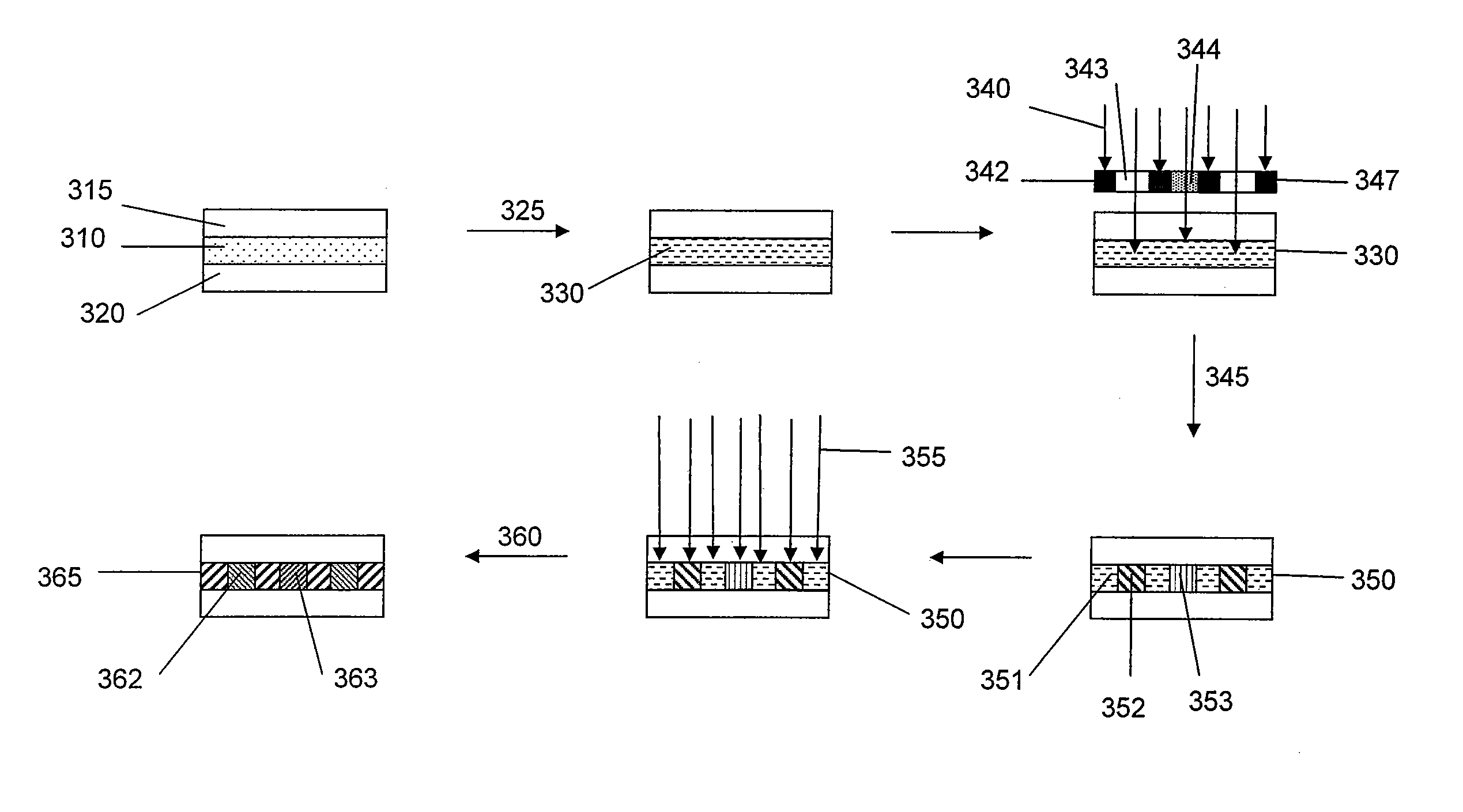
[0084] The mixture of Example 2 was transferred to a glass plate equipped with a wire spacer. The mixture on the plate was degassed to remove trapped air. A thin glass plate was carefully placed over the glass plate and the plates were pressed firmly together, with the degassed mixture sandwiched between. The sandwiched mixture was cured by exposing it to ultraviolet light using a UV lamp (EXFO intensity=16.6 mW / cm2) for 5 minutes. The difference in the refractive index between the sandwiched mixture and the cured film was measured to be 0.024.


PUM

PropertyMeasurementUnit
refractive indexaaaaaaaaaa
thicknessaaaaaaaaaa
temperatureaaaaaaaaaa

Abstract

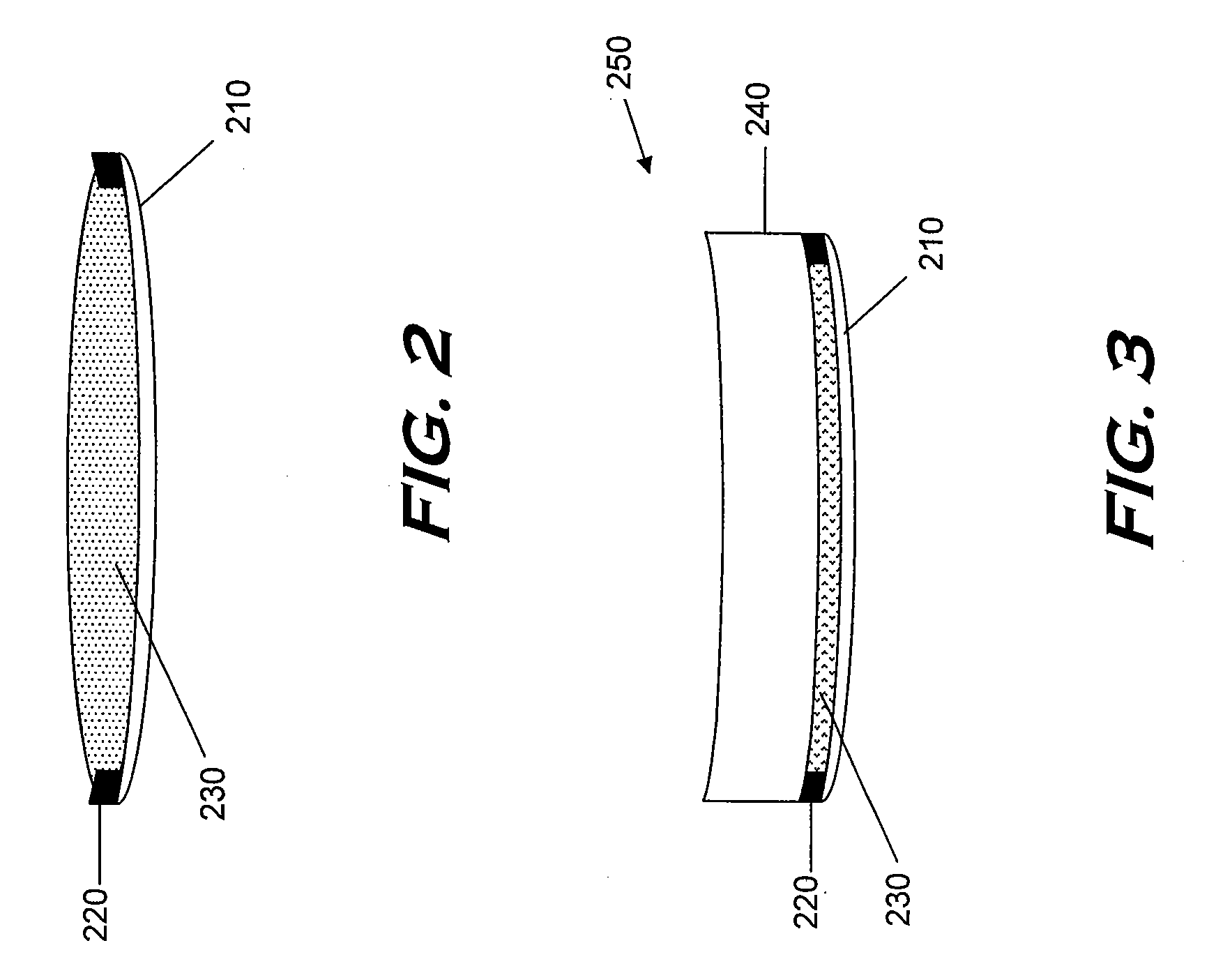
An optical element includes a first lens; a cover; and a cured matrix polymer sandwiched between the first lens and the cover; the matrix polymer, prior to curing, having a monomer mixture dispersed therein; the matrix polymer being selected from the group consisting of polyester, polystyrene, polyacrylate, thiol-cured epoxy polymer, thiol-cured isocyanate polymer, and mixtures thereof; and the monomer mixture comprising a thiol monomer and at least one second monomer selected from the group consisting of ene monomer and yne monomer.

Description

CROSS-REFERENCE TO RELATED APPLICATIONS [0001] This application is continuation of U.S. application Ser. No. 10 / 936,030, filed Sep. 7, 2004, and entitled Monomers and Polymers for Optical Elements, the entirety of which is incorporated herein by reference.BACKGROUND OF THE INVENTION [0002] 1. Field of the Invention [0003] This invention relates to monomeric and polymeric materials, and to stabilized mixtures of monomeric and polymeric materials useful for making optical elements such as lenses. [0004] 2. Description of the Related Art [0005] Optical elements such as eyeglass lenses are typically made by casting, grinding and / or polishing lens blanks made from glass or plastics such as polycarbonate, Finalite™ (Sola), MR-8 polymer (Mitsui), and diethylene glycol bis(allylcarbonate)polymer (CR-39) (PPG Industries). However, lenses made using these materials and fabrication techniques are only capable of correcting relatively simple optical distortions. Other fabrication techniques and...

Claims


Application Information

Patent Timeline
Patent Type & Authority Applications(United States)
IPC IPC(8): B32B27/06G02B1/10
CPCC08F212/34C08F212/36C08F283/00C08F290/00C08F290/06C08F290/14C08F291/00G02C2202/14C08G75/045C08L25/18G02B3/0087C08L2666/04Y10T428/31855C08L23/00C08F112/08C08G75/12
Inventor JETHMALANI, JAGDISHDREHER, ANDREAS W.ABDEL-SADEK, GOMAACHOMYN, JEFFREYLI, JIEMINGQADDOURA, MAHER
Owner ESSILOR INT CIE GEN DOPTIQUE
Learn More