
Porous osteoimplant

a technology of porous bone and implant, which is applied in the field of porous bone implants, can solve the problems of reducing the bone density around the implant site, fractures and other orthopedic injuries that take a long time to heal, and unable to support physiologic loading, so as to accelerate the remodeling process and promote cellular infiltration

Active Publication Date: 2008-03-20
WARSAW ORTHOPEDIC INC
View PDF96 Cites 169 Cited by
  • Summary
  • Abstract
  • Description
  • Claims
  • Application Information

AI Technical Summary

Benefits of technology

[0007] The present invention is directed to new systems and strategies for bone repair. In particular, the present invention provides porous composites which, upon implantation, promote cellular infiltration from adjacent osseous tissues, thus accelerating the remodeling process. The inventive composites comprise a polymer, such as a biocompatible polymer, and a plurality of particles of inorganic material, bone-derived material, bone substitute material, or composite material. The present invention also provides methods that can be used for the preparation of such composites that involve a supercritical fluid (e.g., supercritical carbon dioxide) treatment. The invention also provides methods and kits for using the inventive porous materials.

Problems solved by technology

While bone wounds can regenerate without the formation of scar tissue, fractures and other orthopedic injuries take a long time to heal, during which the bone is unable to support physiologic loading.
Use of metal implants may result in decreased bone density around the implant site due to stress shielding.
Furthermore, most metal implants are permanent and unable to participate in physiological remodeling.
However, the use of bone grafts is limited by the available shape and size of grafts and the desire to optimize both mechanical strength and degradation rate.
Variations in bone size and shape among patients (and donors) also make bone grafts a less optimal substitute material.
Bone substitute materials and bone chips are quickly remodeled but cannot immediately provide mechanical support.

Method used


Image

  • Porous osteoimplant
  • Porous osteoimplant
  • Porous osteoimplant

Examples


example 1

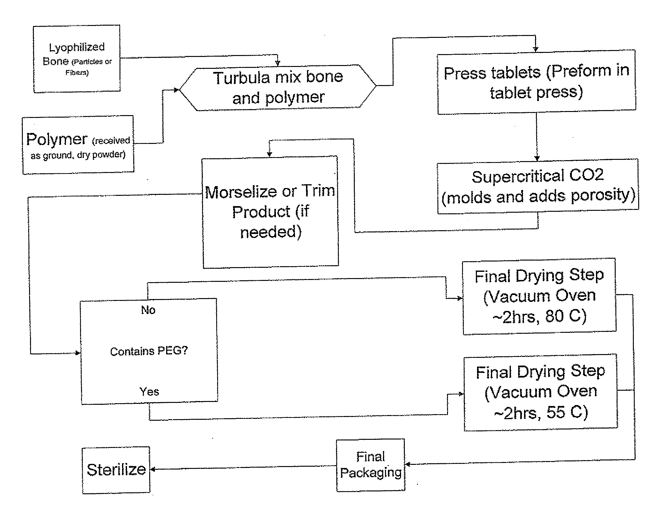
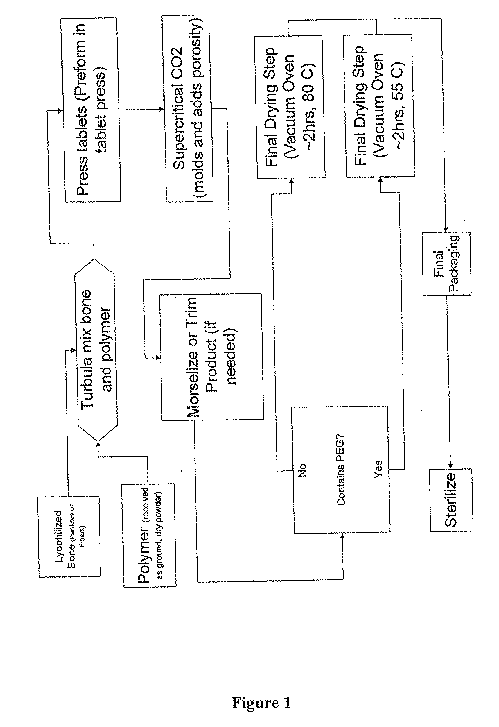
[0165] Mineralized human cortical bone particles (about 200-500 microns), were mixed in a ratio of about 80 / 20 with RESOMER™ 824 particles ground to about the same size. The mixture was tabletted, and a known number of tablets were placed in a stainless steel cylinder that is closed at one end. The cylinder was then placed in a supercritical CO2 chamber and held at 5000 psi for 1 hour at 115° C. The chamber was allowed to cool to 90° C. and then vented, reaching atmospheric pressure in about 20 seconds. The composite resulting from this process had a porosity of about 60-70%. The wet compressive strength was about 3 MPa at 20% engineering strain but reached 4-5 MPa at higher strains.

example 2

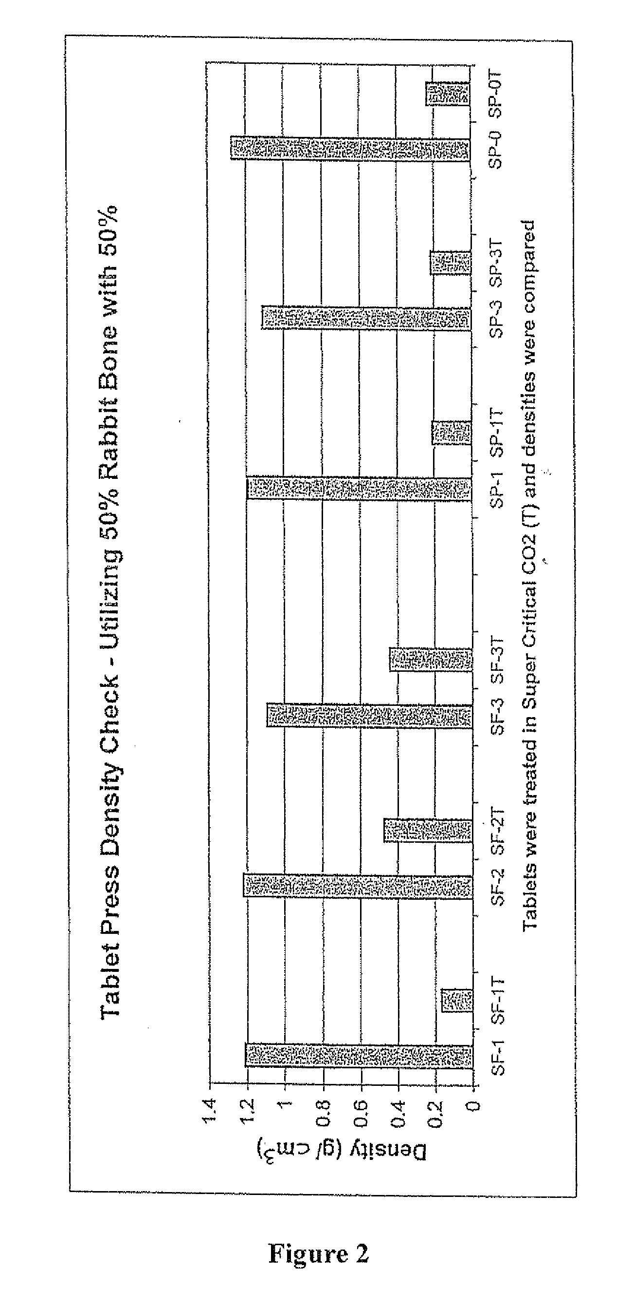
[0166] Composites were prepared as described in Example 1, but with rabbit bone fibers up to about 3 mm long and with a 50 / 50 ratio of rabbit bone fibers and polymer. After supercritical treatment, samples including about half gram of material had porosities of about 61% and about 52%.

example 3

[0167] Composites were prepared as described in Example, but with a 50 / 50 ratio of rabbit bone particles and polymer. The mixture was pre-packed dry at a pressure of about 200 psi and treated with supercritical CO2 as in Example 1. Samples of about 0.9 g of the resulting product had a porosity of about 62% and about 77%.


PUM

PropertyMeasurementUnit
Fractionaaaaaaaaaa
Timeaaaaaaaaaa
Timeaaaaaaaaaa

Abstract

The invention is directed toward porous composites for application to a bone defect site to promote new bone growth. The inventive porous composites comprise a biocompatible polymer and a plurality of particles of bone-derived material, inorganic material, bone substitute material or composite material. In certain embodiments, the porous composites are prepared using a method that includes a supercritical fluid (e.g., supercritical carbon dioxide) treatment. The invention also discloses methods of using these composites as bone void fillers.

Description

RELATED APPLICATIONS [0001] This application claims priority from Provisional Application No. 60 / 760,752 filed on Jan. 19, 2006 and entitled “Porous Bone Void Filler” and Provisional Application No. 60 / 760,239 filed on Jan. 19, 2006 and entitled “Bone Substitute Material”. Each of the provisional applications is incorporated herein by reference in its entirety.FIELD OF THE INVENTION [0002] This invention pertains to porous osteoimplants. BACKGROUND OF THE INVENTION [0003] Bone is a composite material composed of impure hydroxyapatite, collagen, and a variety of non-collagenous proteins, as well as embedded and adherent cells. Bone can be processed into an implantable biomaterial, such as an allograft, for example, by removing the cells, leaving behind the extracellular matrix. The processed bone material can have a variety of properties, depending upon the specific processes and treatments applied to it, and may incorporate characteristics of other biomaterials with which it is comb...

Claims


Application Information

Patent Timeline
IPC IPC(8): A61K35/32A61F2/28A61P19/00
CPCA61F2/28A61F2002/30062A61F2002/30677A61F2210/0004A61F2310/00359A61F2310/00365A61L27/446A61L27/46A61L27/56A61F2310/00293A61P19/00
Inventor SHIMP, LAWRENCE A.WINTERBOTTOM, JOHNKAES, DAVID R.BELANEY, RYAN M.BHATTACHARYYA, SUBHABRATA
Owner WARSAW ORTHOPEDIC INC
Learn More