
Polycrystalline diamond composites

a technology of polycrystalline diamonds and composites, applied in the field of polycrystalline diamond composites, can solve the problems of reducing the penetration rate or speed of the drill bit through such hard formations, reducing the ability and effectiveness of the cutting element to remove the formation, and reducing so as to facilitate the attachment of the resulting construction and improve the degree of thermal stability and/or wear/abrasion resistan

Inactive Publication Date: 2008-03-27
SMITH INT INC
View PDF65 Cites 142 Cited by
  • Summary
  • Abstract
  • Description
  • Claims
  • Application Information

AI Technical Summary

Benefits of technology

[0019] Polycrystalline diamond composites can be made by forming a plurality of sintered granules comprising an ultra-hard material. These sintered granules are then combined with diamond grains to form a mixture. The mixture is then subjected to a high pressure / high temperature process in the presence of a catalyst material to sinter the diamond grains thereby forming a material microstructure comprising a plurality of discrete regions formed by the plurality of granules dispersed within a polycrystalline diamond region formed by the sintered diamond grains. As noted above, the so-formed plurality of discrete regions is different from the polycrystalline diamond region in at least one of the following respects, thermal stability, abrasion resistance, wear resistance, ultra-hard material density.
[0020] Polycrystalline diamond composite can also be made by forming a plurality of unsintered granules comprising an ultra-hard material and a first binder material, and combining the plurality of granules with diamond grains to form a mixture. The mixture is then subjected to a first high pressure / high temperature condition in the presence of a second binder material to melt the first binder and sinter the plurality of granules. The mixture is then subjected to a second high pressure / high temperature condition in the presence of the second binder material to melt the second binder to sinter the diamond grains, thereby forming a material microstructure comprising a plurality of discrete regions formed by the plurality of sintered granules that is dispersed within a polycrystalline diamond region formed by the sintered diamond grains. As noted above, the so-formed plurality of discrete regions is different from the polycrystalline diamond region in at least one of the following respects, thermal stability, abrasion resistance, wear resistance, ultra-hard material density.
[0021] Such polycrystalline diamond constructions are engineered to have an improved degree of thermal stability and / or wear / abrasion resistance when compared to conventional PCD materials, and are further constructed to include a substrate material bonded to the polycrystalline body to facilitate attachment of the resulting construction to an application device by conventional method such as welding or brazing and the like. Such polycrystalline diamond construction also provide a desired degree of impact resistance and strength that is the same as or that exceeds that of conventional PCD.

Problems solved by technology

A problem known to exist with conventional PCD construction, i.e., those comprising a uniform or homogeneous microstructure of bonded together diamond grains is that when used as a cutting element on a drill bit, the rate of penetration (ROP) or speed in which the drill bit progresses through such hard formations may often be reduced, or slowed.
This is believed due to the fact that the homogeneous structure of the PCD cutting element is unable to provide cutting surfaces or edges that will optimally engage and remove formation material.
Such rounding or dulling of the cutting edge also reduces the ability and effectiveness of the cutting element to remove the formation material
A further problem known to exist with such conventional PCD materials is that they are vulnerable to thermal degradation, when exposed to elevated temperature cutting and / or wear applications, caused by the differential that exists between the thermal expansion characteristics of the interstitial catalyst material and the thermal expansion characteristics of the intercrystalline bonded diamond.
Such differential thermal expansion is known to occur at temperatures of about 400° C., can cause ruptures to occur in the diamond-to-diamond bonding, and eventually result in the formation of cracks and chips in the PCD structure, rendering the PCD structure unsuited for further use.
Specifically, the solvent metal catalyst is known to cause an undesired catalyzed phase transformation in diamond (converting it to carbon monoxide, carbon dioxide, or graphite) with increasing temperature, thereby limiting practical use of the PCD material to about 750° C.
While this approach produces an entire PCD body that is substantially free of the solvent catalyst material, is it fairly time consuming.
Additionally, a problem known to exist with this approach is that the lack of solvent metal catalyst within the PCD body precludes the subsequent attachment of a metallic substrate to the PCD body by solvent catalyst infiltration.
However, the difference in thermal expansion between the TSP body and the substrate, and the poor wetability of the TSP body diamond surface due to the substantial absence of solvent metal catalyst, makes it very difficult to bond TSP to conventionally used substrates.
Since such TSP bodies are devoid of a metallic substrate they cannot (e.g., when configured as a cutting element for use on a bit for subterranean drilling) be attached to such drill bit by conventional brazing process.
The use of such TSP bodies in this particular application necessitates that the TSP body itself be mounted to the drill bit by mechanical or interference fit during manufacturing of the drill bit, which is labor intensive, time consuming, and does not provide a most secure method of attachment.

Method used


Image

  • Polycrystalline diamond composites
  • Polycrystalline diamond composites
  • Polycrystalline diamond composites

Examples


Embodiment Construction

[0032] In one aspect, embodiments of the invention relate to PCD composite constructions having a plurality of discrete regions dispersed in a polycrystalline diamond region, where the discrete regions have properties of thermal stability, polycrystalline density, binder or catalyst material type and / or content, wear resistance, and / or abrasion resistance that differ from that of a polycrystalline diamond material surrounding the plurality of discrete regions. Moreover, embodiments of this invention relate to cutting and / or wear elements including such PCD composite constructions and methods of forming the same.

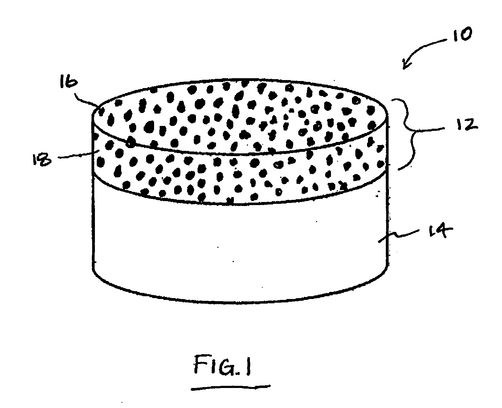
[0033]FIG. 1 illustrates a PCD composite construction, prepared according to principles of this invention, that is provided in the form of a compact 10, e.g., one that can be configured for use as a cutting and / or a wear element for an end use application. The PCD composite compact 10 includes a polycrystalline diamond body 12 that is disposed on a substrate 14. The polycrys...


PUM

PropertyMeasurementUnit
Temperatureaaaaaaaaaa

Abstract

Polycrystalline diamond composites comprise a polycrystalline diamond body having a plurality of ultra-hard discrete regions dispersed within a polycrystalline diamond second region. The plurality of discrete regions has an density different from of the polycrystalline diamond second region. A metallic substrate can be joined to the body. The discrete regions can be relatively more thermal stable than, have a higher diamond density than, and / or may comprise a binder material that is different from the polycrystalline diamond second region. Polycrystalline diamond composites can be formed by combining already sintered granules with diamond grains to form a mixture, and subjecting the mixture to high pressure / high temperature conditions, wherein the granules form the plurality of discrete regions, or can be made by forming a plurality of unsintered granules, combining them with diamond grains to form a mixture, and then subjecting the mixture to first and second high pressure / high temperature conditions.

Description

FIELD OF THE INVENTION [0001] The invention relates generally to polycrystalline diamond composites and, more particularly, to polycrystalline diamond composites that have been specially engineered to have a material microstructure comprising a plurality of discrete regions having thermal stability, abrasion resistance, wear resistance, polycrystalline material density, and / or catalyst material type and / or content that is different from that of surrounding matrix or continuous polycrystalline diamond region to provide desired improved properties of wear resistance, abrasion resistance, and / or thermal stability to the overall composite. BACKGROUND OF THE INVENTION [0002] Polycrystalline diamond (PCD) has been widely used as wear and / or cutting elements in industrial applications, such as for drilling subterranean formations and metal machining for many years. Typically, such PCD cutting elements are provided in the form of a compact that comprises a body formed from PCD (or other sup...

Claims


Application Information

Patent Timeline
IPC IPC(8): E21B10/46B01J3/06C01B31/06
CPCE21B10/5676E21B10/567C04B35/528E21B10/46
Inventor SHEN, YUELINZHANG, YOUHEHUANG, SUJIANKESHAVAN, MADAPUSI K.
Owner SMITH INT INC
Learn More