Laser crystallization apparatus and crystallization method

a laser crystallization and crystallization apparatus technology, applied in the field of laser crystallization apparatus and crystallization method, can solve the problems of limitation in the performance of tft, inability to control the position of crystallized grains, and inability to position a place where crystallized grains are to be formed,

Inactive Publication Date: 2008-03-27
SHIMADZU CORP
View PDF19 Cites 19 Cited by
  • Summary
  • Abstract
  • Description
  • Claims
  • Application Information

AI Technical Summary

Benefits of technology

[0013]The above-mentioned problems are solved by a laser crystallization ...

Problems solved by technology

However, according to the method, the crystal grain size in a crystallized semiconductor film is as small as 0.5 μm or less, and position of the crystallized grains can not be controlled.
Therefore, a crystal grain boundary could be present in a channel region of the TFT, so that there is a limitation in performance of the TFT, for example, u...

Method used


Image

  • Laser crystallization apparatus and crystallization method
  • Laser crystallization apparatus and crystallization method
  • Laser crystallization apparatus and crystallization method

Examples


first embodiment

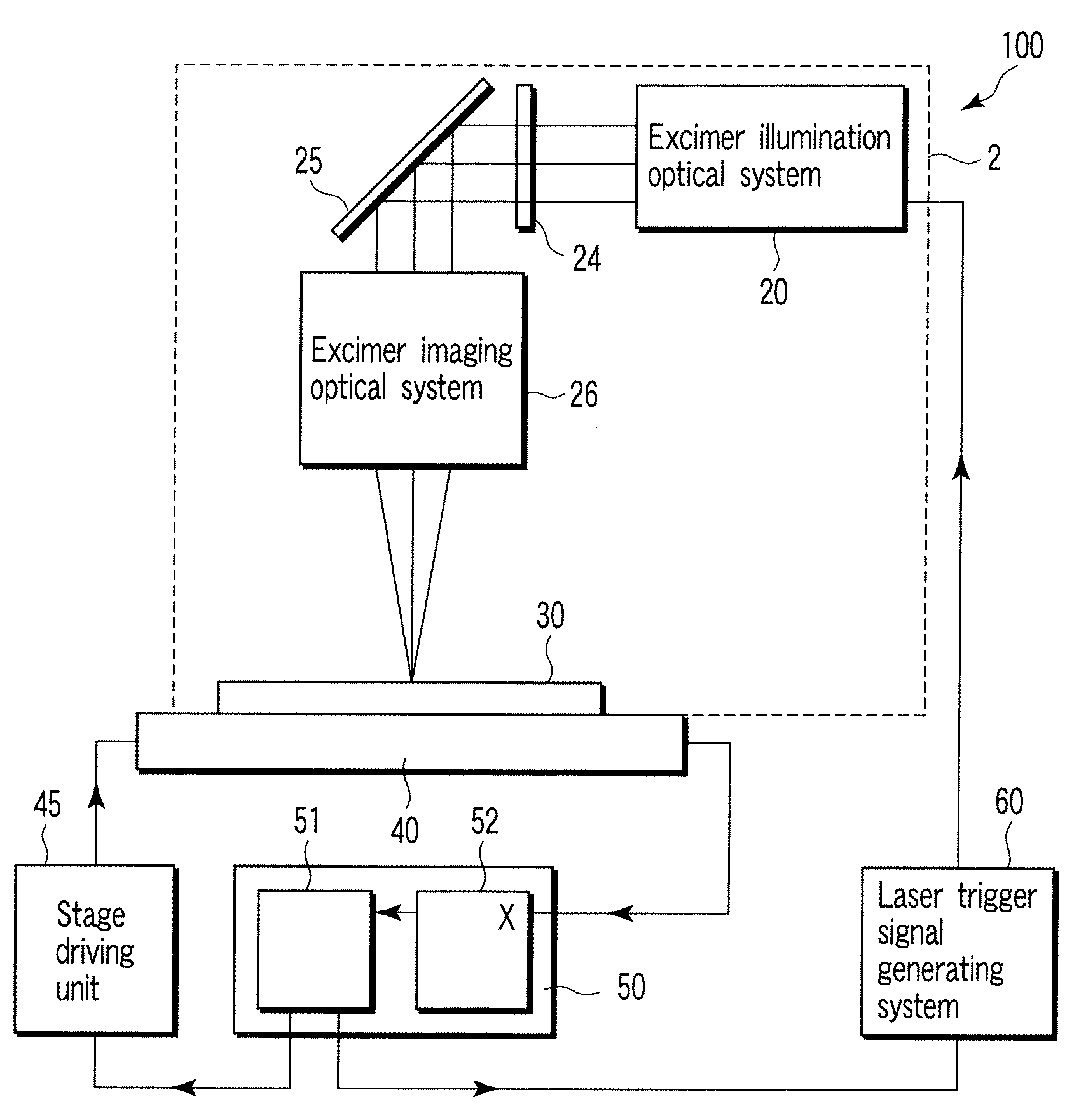
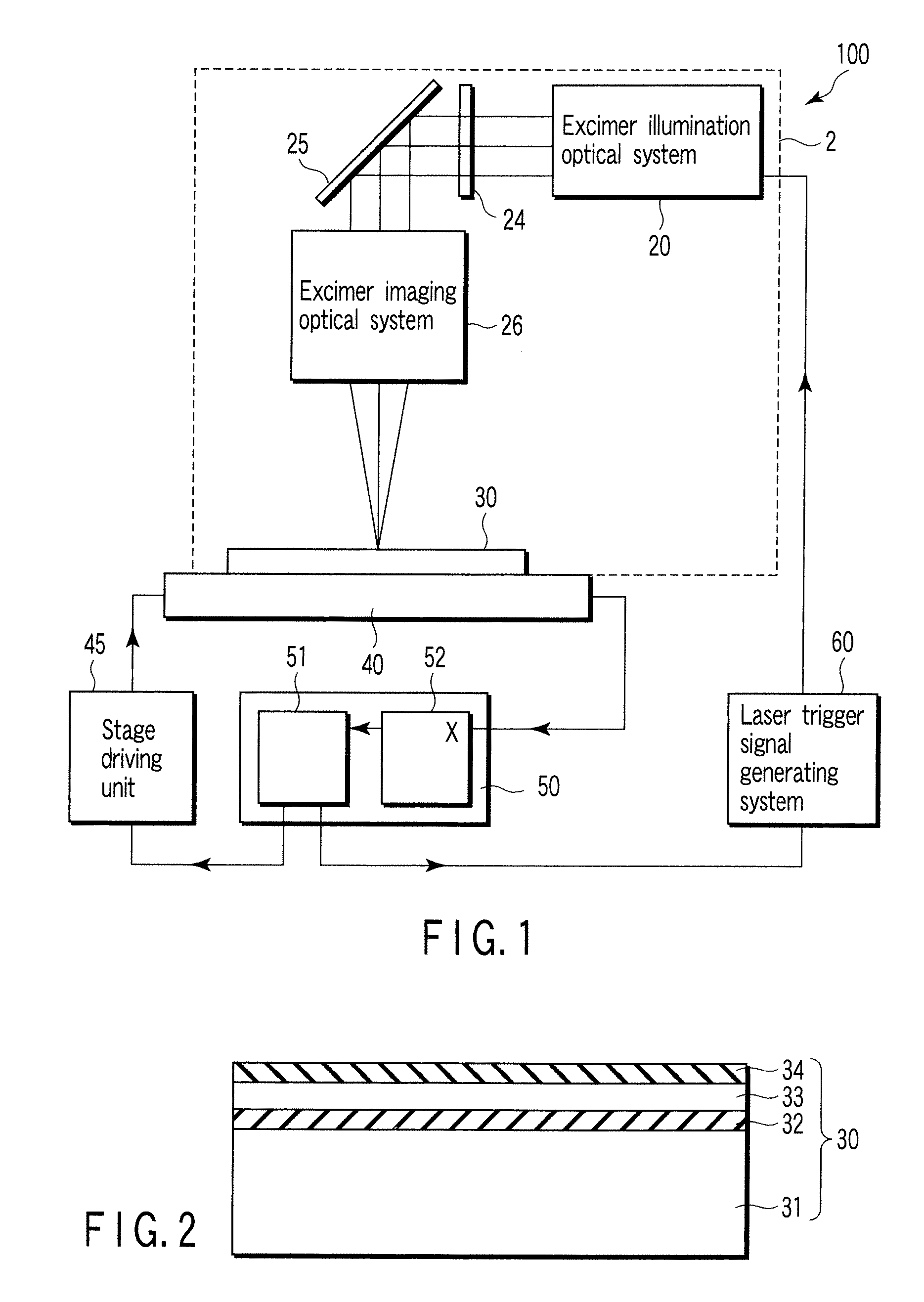
[0040]One example of a laser crystallization apparatus 100 according to a first embodiment of the present invention is shown in FIG. 1. The laser crystallization apparatus 100 comprises a crystallization optical system 2, a substrate holding stage 40, a stage position measuring system 50, and a system which generates a signal for indicating the generation of crystallizing laser light, for example, a laser trigger signal generating system 60. The substrate holding stage 40 is continuously moved at a predetermined velocity without stopping during a crystallization process period. The laser crystallization apparatus 100 irradiates crystallizing laser light to a predetermined position on a processing substrate 30 based on measurement of the predetermined position on the substrate holding stage by the stage position measuring system 50.

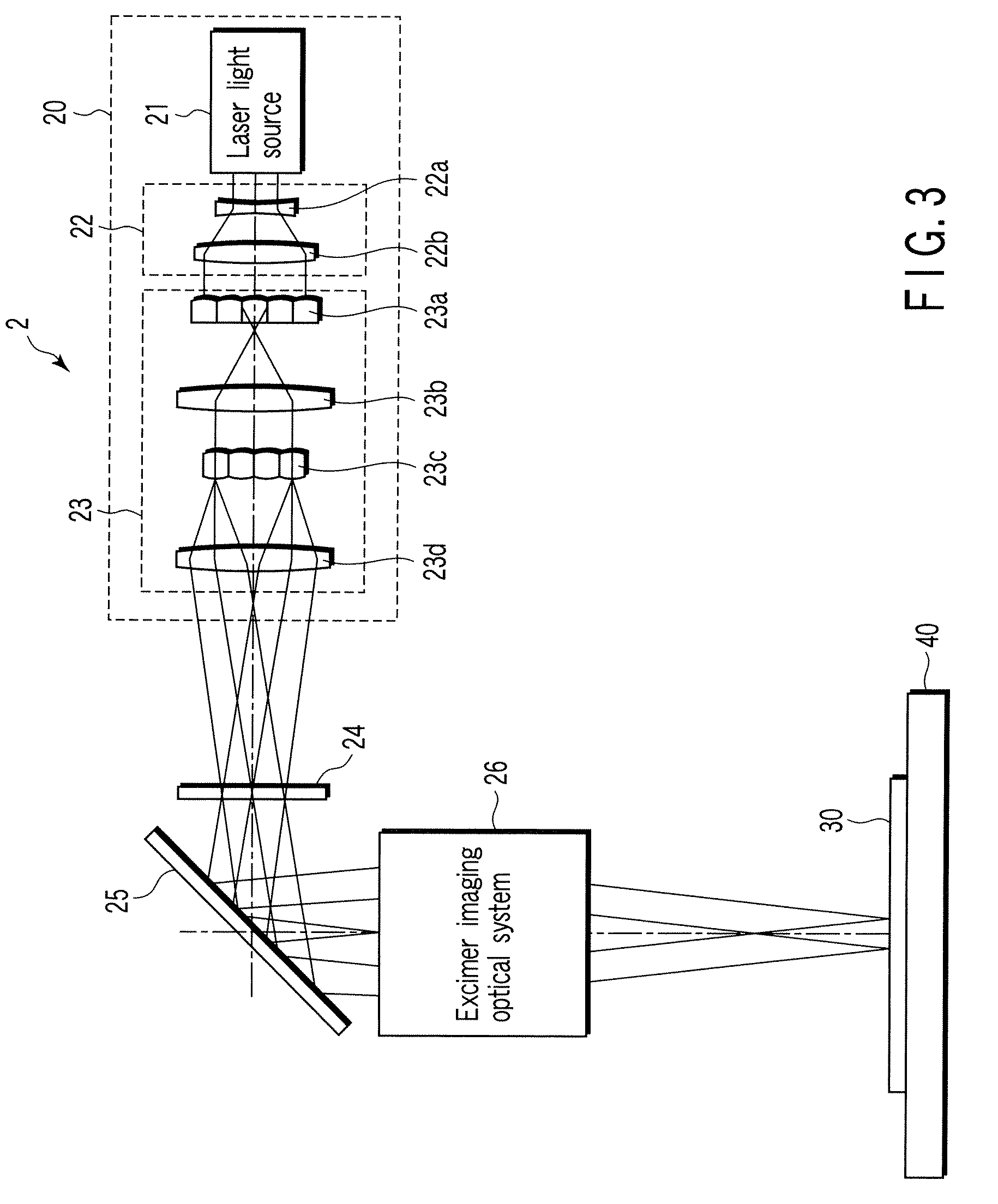
[0041]The crystallization optical system 2 comprises a light source, for example, an excimer illumination optical system 20, and a sequential arrangement ...

second embodiment

[0077]In the first embodiment, the positioning accuracy of the moving substrate holding stage in an X direction is improved by correcting variation in the moving velocity of the stage. However, even in a highly accurately controlling device of the substrate holding stage 40 using the air bearing / linear motor driving mechanism, it may be achieved a straightness in the Y and Z directions of about 10 μm at the best in the case of a high-velocity X-direction movement of about 500 mm / sec. Therefore, the laser crystallization apparatus 100 which is required to irradiate crystallizing laser light with a positional accuracy of 1 μm or less needs to make another simultaneous positional correction in the Y and / or Z direction while moving the substrate holding stage 40 in the X direction.

[0078]A second embodiment of the present invention concerns a laser crystallization apparatus 500 which carries out crystallization so that a processing substrate is continuously moved in X direction while cor...

third embodiment

[0087]In the first and second embodiments, one crystallization optical system 2 has been used, the third embodiment concerns an example of a laser crystallization apparatus having a plurality of crystallization optical systems 2N.

[0088]FIG. 6 is a diagram showing one example of a laser crystallization apparatus 600 in the present embodiment. The same numerals are assigned to the same parts as those in FIG. 5, and these parts are not described in detail. In FIG. 6, for simplicity of explanation, there is shown an example in which two crystallization optical systems, for example, a first and second crystallization optical systems 2A and 2B, are arranged apart in a Y direction, which is vertical to the scanning direction (X direction) of a substrate holding stage 40. However, the number of crystallization optical systems and the arrangement thereof are not limited to the above. In FIG. 6, alphabetical signs are added to the numerical signs of the same optical components to distinguish ...


PUM

PropertyMeasurementUnit
Grain sizeaaaaaaaaaa
Heightaaaaaaaaaa
Distributionaaaaaaaaaa

Abstract

A laser crystallization apparatus and a crystallization method with a high throughput are provided. Laser light having a predetermined light intensity distribution is irradiated to a semiconductor film to melt and crystallize, wherein a irradiation position is placed very quickly and with a high positional accuracy, thereby forming the semiconductor film having a large crystal grain size. A laser crystallization apparatus according to one aspect of the present invention comprises a crystallizing laser light source, a phase shifter modulating pulse laser light to have the predetermined light intensity distribution, an excimer imaging optical system, a substrate holding stage mounting a processing substrate and continuously moving in the predetermined direction, a position measuring means, and a signal generating means indicating generation of the pulse laser light based on the position measurement of the stage by the position measuring means.

Description

CROSS-REFERENCE TO RELATED APPLICATIONS[0001]This application is based upon and claims the benefit of priority from prior Japanese Patent Application No. 2005-362092, filed Dec. 15, 2005, the entire contents of which are incorporated herein by reference.BACKGROUND OF THE INVENTION[0002]1. Field of the Invention[0003]The present invention relates to a laser crystallization apparatus and a crystallization method, and more specifically, to a laser crystallization apparatus and a crystallization method in which positioning is performed very quickly and with a high positional accuracy to irradiate laser light for crystallization.[0004]2. Description of the Related Art[0005]A thin film transistor (TFT) formed on a semiconductor film, for example, a silicon film, provided on a large-area substrate, for example, a glass substrate, is used as, for example, a switching device for switched display in an active matrix type liquid crystal display device.[0006]For the crystallization of a non-sin...

Claims


Application Information

Patent Timeline
IPC IPC(8): A61N5/00H01L21/268
CPCB23K26/04B23K26/0608B23K26/043B23K26/0676H01L21/2026B23K26/063B23K26/0622H01L21/02686H01L21/02422H01L21/02488H01L21/02678H01L21/02532H01L21/02595H01L21/02381H01L21/02691H01L21/02667
Inventor TAKAMI, YOSHIOTAGUCHI, TATSUHIRO
Owner SHIMADZU CORP
Why Eureka
Try Eureka