LED display module

a technology of led display module and display module, which is applied in the direction of identification means, dismountable cabinets, cabinets, etc., can solve the problems of inconsistency in viewing and module uniformity, corrosion of the coating on the led circuit board, and no longer properly sealing the led display module, so as to improve the visibility of the leds, improve weather and climatological sealing, and improve the suppression of emi (electromagnetic interference)

Active Publication Date: 2008-04-03
DAKTRONICS
View PDF61 Cites 124 Cited by
  • Summary
  • Abstract
  • Description
  • Claims
  • Application Information

AI Technical Summary

Benefits of technology

[0010]The general purpose of the present invention is to provide an LED display module having features for improvement over prior art devices by offering novel features for improved visibility of the LEDs, improved weather and climatological sealing, improved EMI (electromagnetic interference) suppression, improved heat dissipation and improved airflow. The LED display module of the present invention includes multiple LED display assemblies having a rear cover secured to the back side thereof.

Problems solved by technology

In either case, a large visible white area of the LED package sides surrounding the LED packages adversely affects the contrast of the display, especially when viewed from the side and viewability was deemed unacceptable due to the presence of a “halo” effect resulting in viewing and module uniformity inconsistency.
After the module had been cycled through expansion and contraction cycles from cold and warm temperatures, the sealant cracked, thereby no longer properly sealing the LED display module.
Additionally, the louver panel was designed to fit tightly against the coated surface of the LED printed circuit board, but this arrangement was not watertight and water flowed into the area between the louver panel and the front surface of the LED circuit board where it pooled, causing corrosion of the coating on the LED circuit board and subsequent premature component failure.
A small rubber gasket was placed on each Mattel pin near its base to plug the gap between the Mattel pin and the respective hole in the LED printed circuit board but this technique did not reliably serve its purpose since water entered through each respective hole.
The problem with some prior art electronic display modules is that excess heat is produced by the number of LEDs and, therefore, the excess heat is not removed effectively.
The heat produced by LED display modules combined with the ambient temperature can produce an unsafe and uneven operating temperature for the LED display modules.
In addition, outdoor use of the LED display modules results in even more heat energy being involved due to solar radiation along with extra heat produced by operating the LEDs at an increased intensity to provide proper display brightness for outdoor conditions.
Another ventilation method of cooling electronic display systems is the use of an air conditioning system which is expensive, takes extra installation time, requires more electrical energy to operate, and is noisy.
Electronic display modules can emit a significant amount of electromagnetic interference (EMI), whereby significant amounts of electromagnetic radiation transmitted from such electronic devices may cause problems such as interference with surrounding electrical devices, such as radios, televisions, cell phones, electronic medical devices and the like, as well as possibly being in violation of FCC regulations for electromagnetic radiations.
However, metal is much heavier than plastic making installation and transportation more difficult.
A problem arises because many of these panels have openings used for ventilation intake and the size of the openings is large enough for significant electromagnetic noise to escape.

Method used


Image

  • LED display module
  • LED display module
  • LED display module

Examples


Embodiment Construction

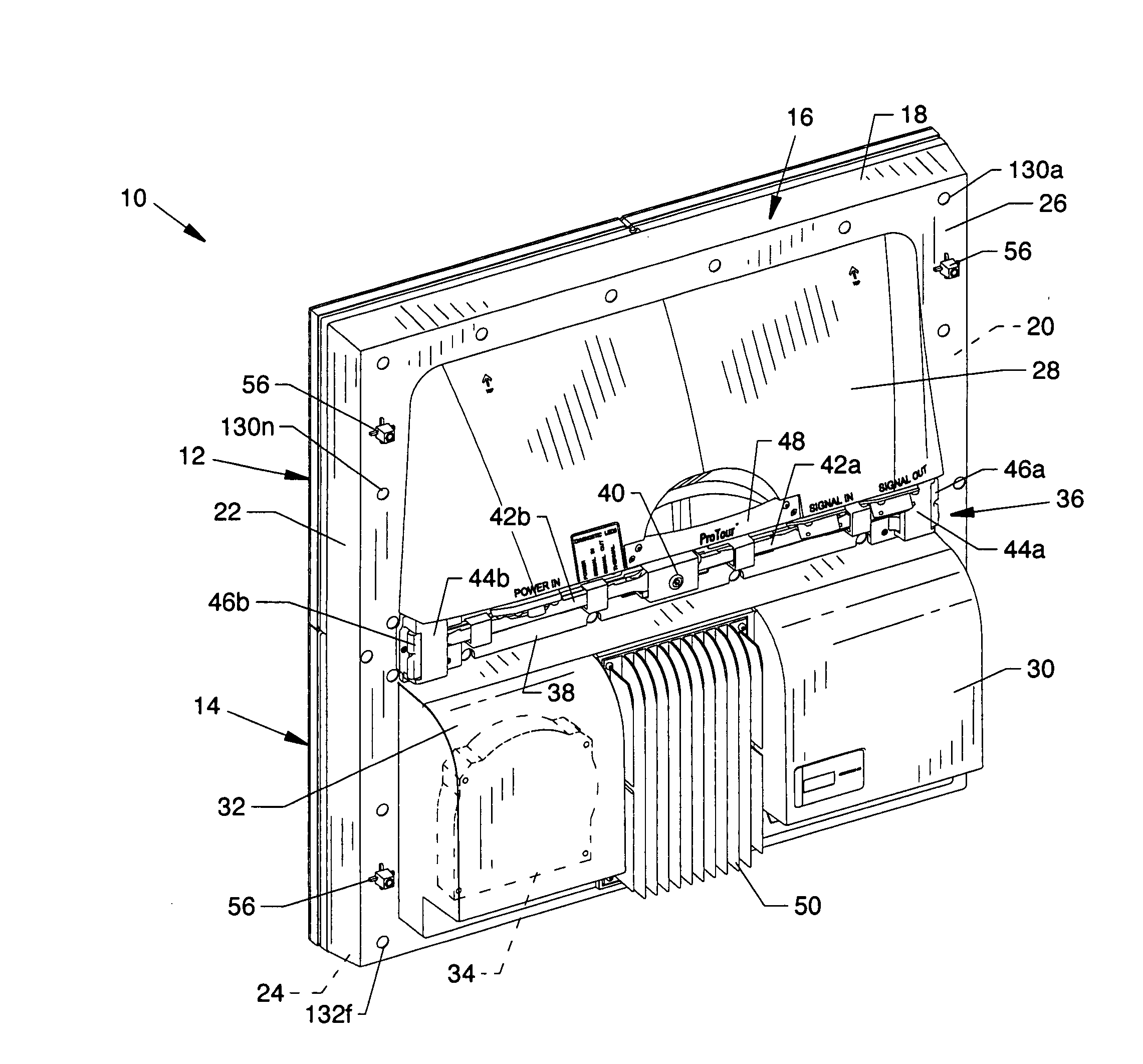
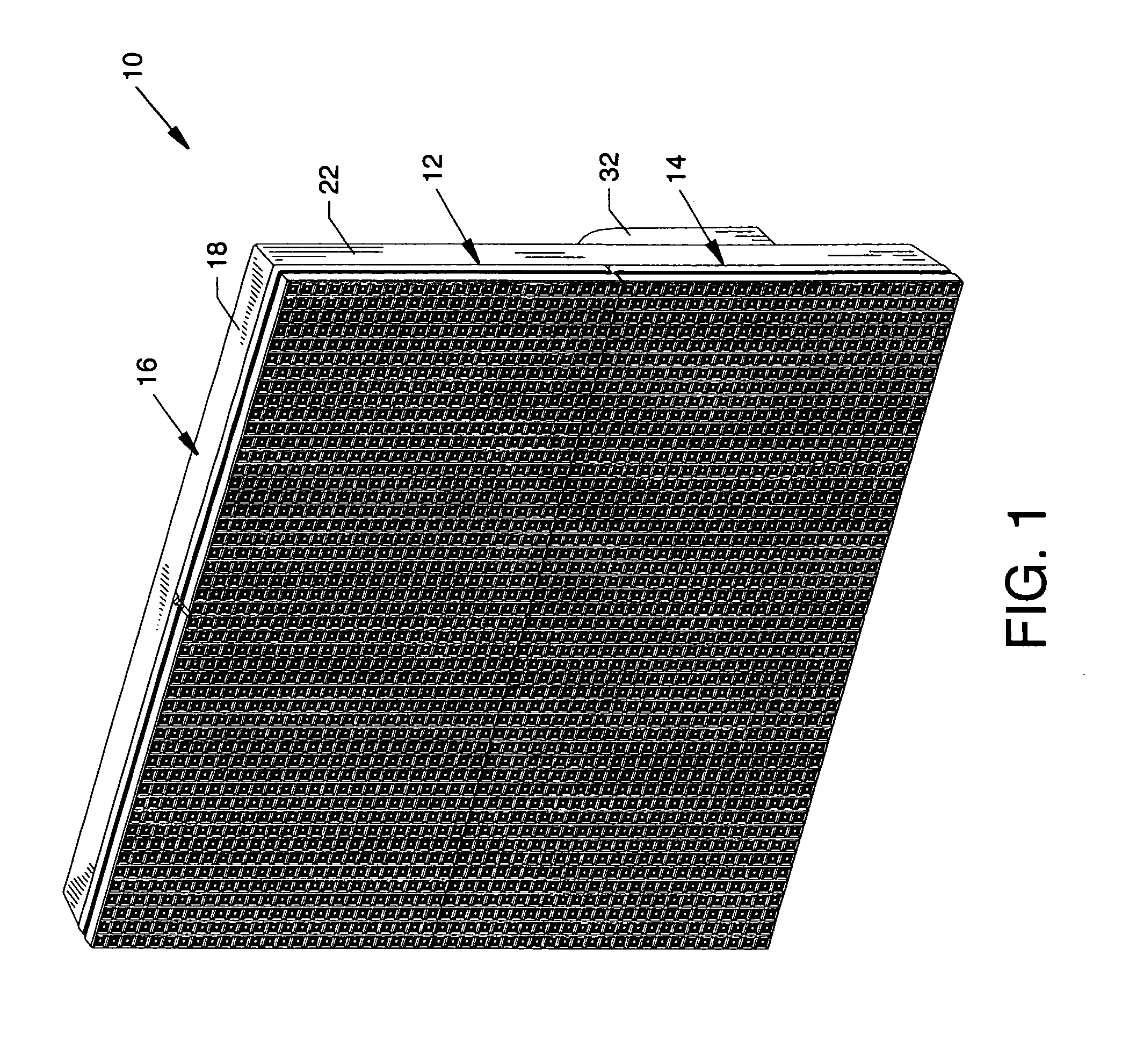
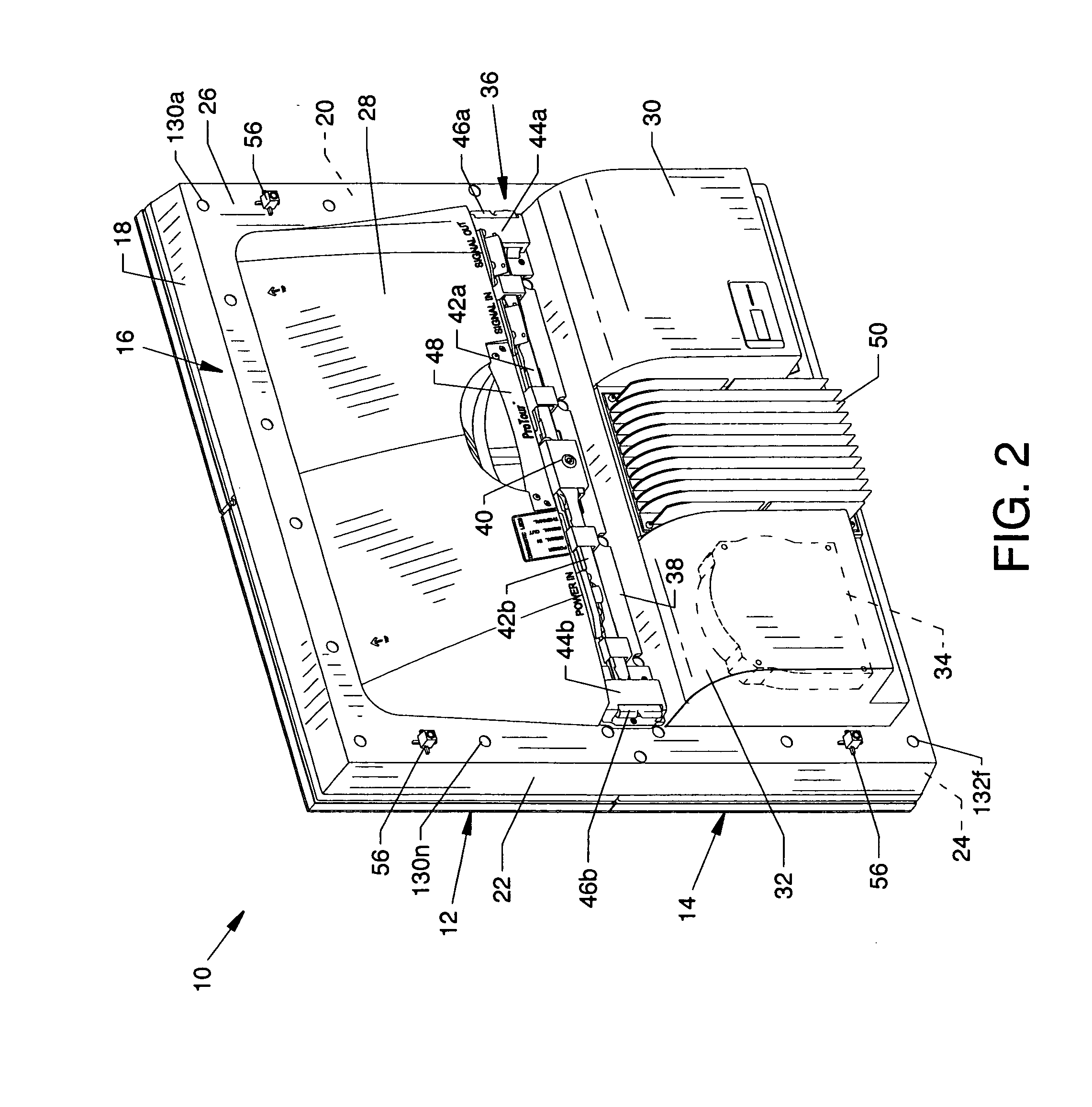
[0062]FIG. 1 is a front view of an LED (light emitting diode) display module 10, the present invention, and FIG. 2 is a rear view of the LED display module 10. Fully or partially visible components as shown in FIG. 1 and / or FIG. 2 include an upper LED display assembly 12, a lower LED display assembly 14, and a configured one-piece rear cover 16 made preferably from polycarbonate combined with EMI protective material. The rear cover 16 includes a top panel 18, opposed side panels 20 and 22, a bottom panel 24, a support panel 26 extending between the rear edges of the top panel 18, the opposed side panels 20 and 22, and the bottom panel 24, an enclosure panel 28 extending from the support panel 26, an air intake enclosure 30 extending from the support panel 26, and a centrifugal air pump enclosure 32 extending from the support panel 26 for housing an internally located centrifugal air pump 34. Also located at the rear of the support panel 26 is an LED display module latching system 36...


PUM


Abstract

An LED display module having features for improvement over prior art devices by providing novel features for improved LED visibility, improved weather and climatological sealing, improved electromagnetic interference (EMI) suppression, improved heat dissipation, and improved airflow.

Description

CROSS REFERENCES TO RELATED APPLICATIONS[0001]This patent application is related to patent application Ser. No. 11 / 271,404 filed Nov. 10, 2005 entitled “Stackable Electronic Sign System And Mounting Structures Therefor,” which is pending. This patent application is also related to patent application Ser. No. 10 / 688,304 entitled “Electronic Display Module Having a Four-Point Latching System for Incorporation into an Electronic Sign and Process”, filed on Oct. 17, 2003, pending. patent application Ser. No. 10 / 688,304 claims priority from the earlier filed U.S. Provisional Application No. 60 / 647,268 filed Jan. 25, 2005, entitled “Electronic Sign”. The prior applications are hereby incorporated into this application by reference as if fully set forth herein.BACKGROUND OF THE INVENTIONField of the Invention[0002]The present invention is for an LED display module and, more particularly, an LED display module preferably incorporated into use with a connector framework such as featured in p...

Claims


Application Information

Patent Timeline
Patent Type & Authority Applications(United States)
IPC IPC(8): A47B47/00
CPCG09F9/33H05K5/061G09F9/3026H05K9/0054H05K7/20972
Inventor NEARMAN, NATHAN LANEMUTSCHELKNAUS, SHANNON LEEMUELLER, MATT RAYWENDLER, BRETT DAVIDBRAVEK, ERIC STEVENLUTZ, ROBERT JAMESHANSEN, RYAN MARKFANNING, NICK JOESEPH
Owner DAKTRONICS
Why Eureka
Try Eureka