Apparatus and method for delivering uniform fluid flow in a chemical deposition system

a technology of uniform fluid flow and chemical deposition system, which is applied in the direction of spraying apparatus, coatings, spray nozzles, etc., can solve the problems of reducing budgets, shrinking dimensions, and increasing difficulty in void-free filling of high aspect ratio (ar) spaces (ar>3.0:1)

Inactive Publication Date: 2008-04-03
NOVELLUS SYSTEMS
View PDF37 Cites 72 Cited by
  • Summary
  • Abstract
  • Description
  • Claims
  • Application Information

AI Technical Summary

Benefits of technology

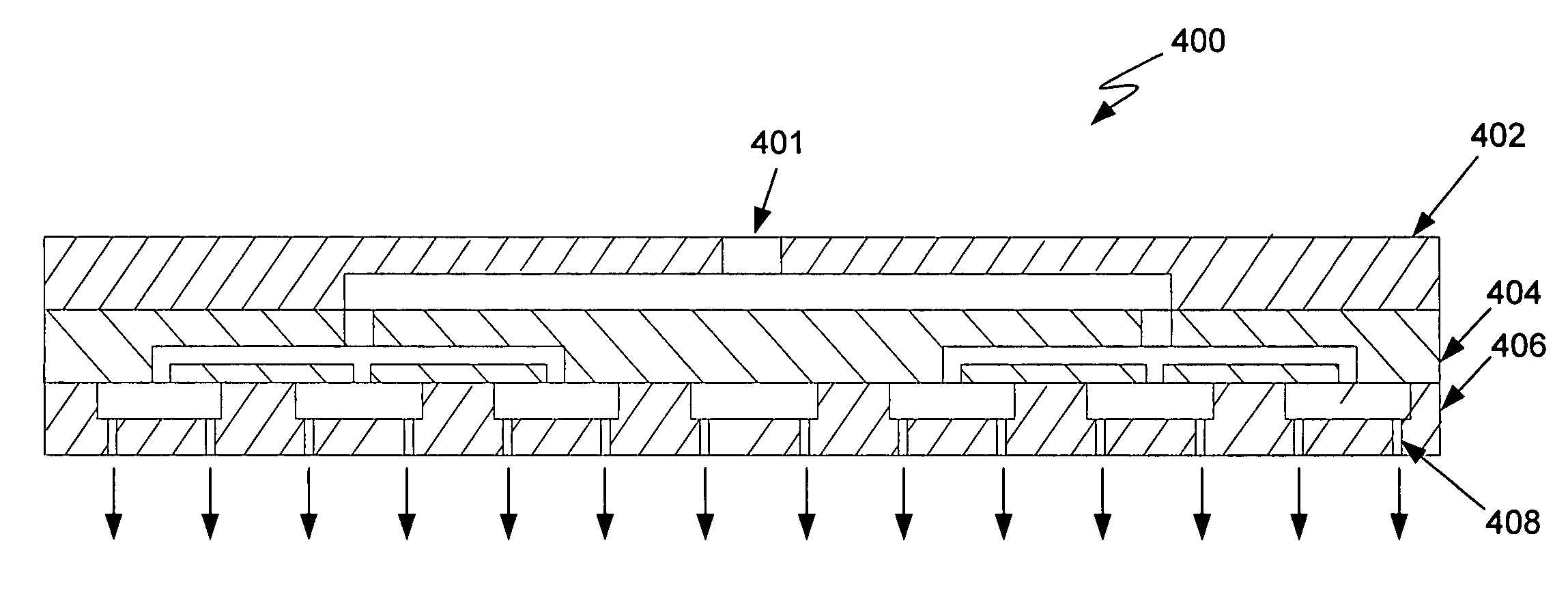
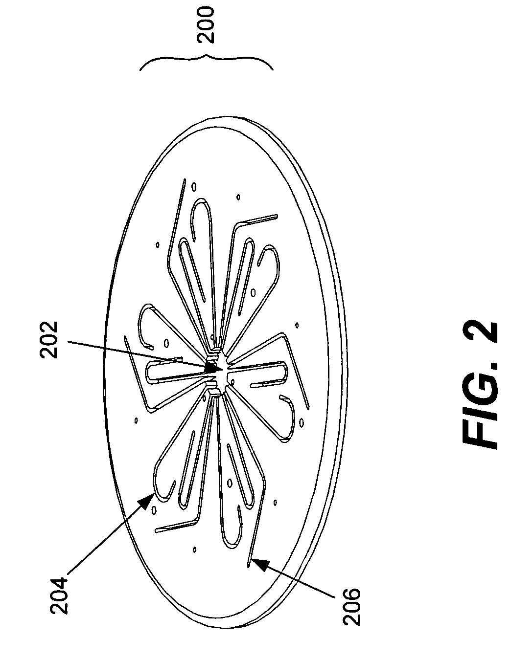
[0010]The present invention provides an apparatus and method for uniform fluid delivery to a substrate using a diffuser. The diffuser is designed with a series of fluid (gas and/or liquid) passages of equal effective length/flow resistance, such that as the fluid passes through the diffuser, the gas exits all areas at the same time and with the same mass flux. These passages may not be physically the same, however they have the same effective length and flow

Problems solved by technology

As device dimensions shrink and thermal budgets are reduced, void-free filling of high aspect ratio (AR) spaces (AR>3.0:1) becomes increasingly difficult due to limitations of existing deposition processes.
For structures representative of the 65 nm and 45 nm technology nodes and beyond, engineering the gap-fill process becomes structure dependent, hence the process requi

Method used


Image

  • Apparatus and method for delivering uniform fluid flow in a chemical deposition system
  • Apparatus and method for delivering uniform fluid flow in a chemical deposition system
  • Apparatus and method for delivering uniform fluid flow in a chemical deposition system

Examples


Embodiment Construction

[0020]In the following detailed description of the present invention, numerous specific embodiments are set forth in order to provide a thorough understanding of the invention. However, as will be apparent to those skilled in the art, the present invention may be practiced without these specific details or by using alternate elements or processes. In other instances, well-known processes, procedures and components have not been described in detail so as not to unnecessarily obscure aspects of the present invention.

[0021]Introduction

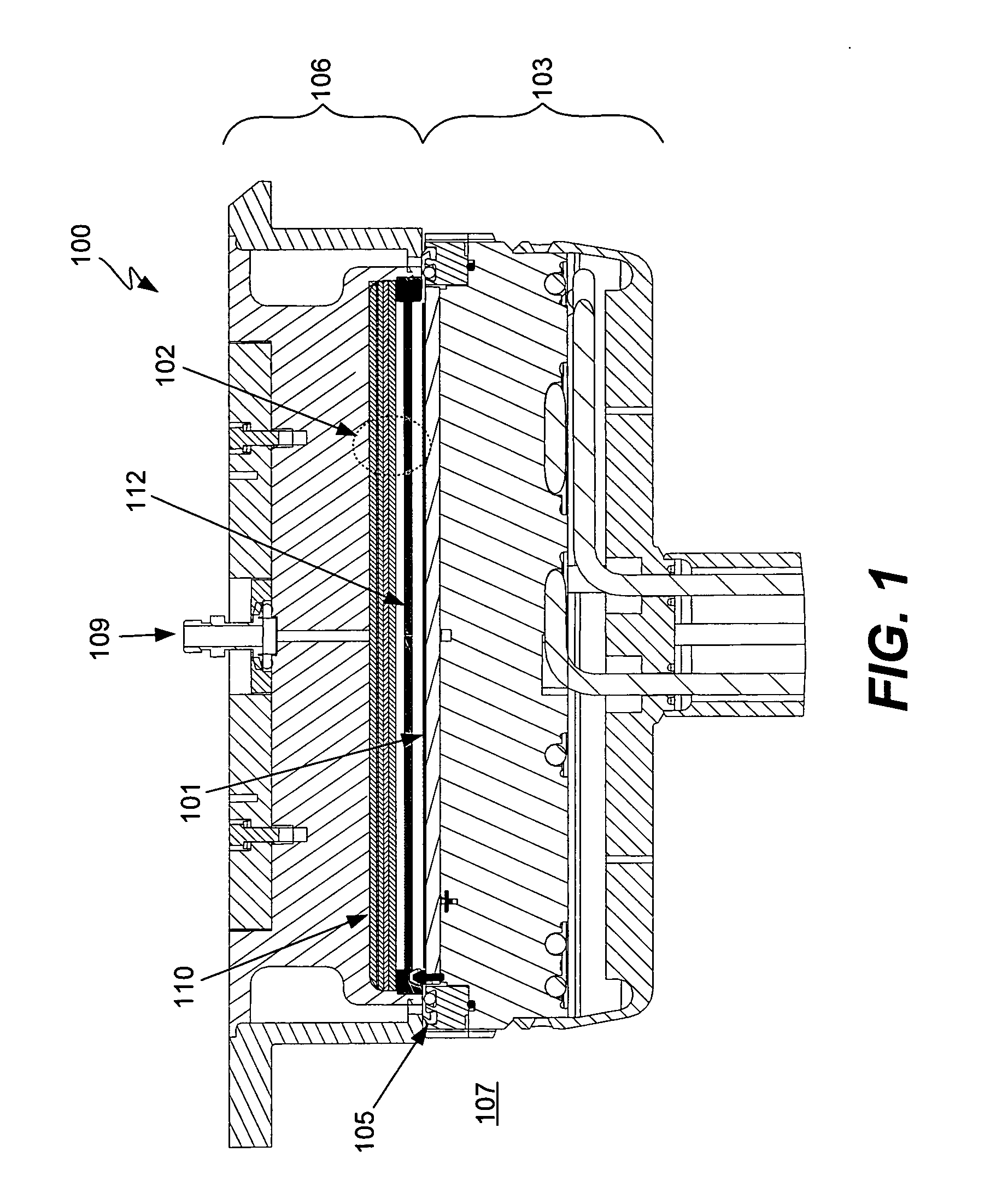
[0022]As indicated, the present invention provides an apparatus and associated method for conducting a chemical deposition. The apparatus and method are particularly applicable to use in conjunction with a semiconductor fabrication based dielectric deposition process that requires separation of self-limiting deposition steps in a multi-step dielectric deposition process (e.g., pulsed layer deposition (PDL) processing for catalyst and silicon precursor dep...


PUM

PropertyMeasurementUnit
Lengthaaaaaaaaaa
Pressureaaaaaaaaaa
Flow rateaaaaaaaaaa

Abstract

Uniform fluid delivery to a substrate is provider using a diffuser. The diffuser is designed with a series of fluid (gas and/or liquid) passages of equal effective length/flow resistance, such that as the fluid passes through the diffuser, the gas exits all areas at the same time and with the same mass flux. These passages may not be physically the same, however they have the same effective length and flow resistance. The diffuser can be implemented using single or multiple stacked layers, and from several to many passages. The net effect is a uniform gas curtain to the wafer. Since the passages through the diffuser are effectively the same, the uniform gas curtain to the wafer is not sensitive to the quantity of gas, the gas flow rate or the gas pressure. Additionally, a faceplate can optionally be used to smooth out any jet effects of the diffuser exit holes.

Description

BACKGROUND OF THE INVENTION[0001]This invention pertains to apparatus and processes for conducting chemical depositions, and may find particular use in depositing a conformal film of dielectric material with a high degree of surface smoothness particularly suited to high aspect ratio gap fill applications in semiconductor device fabrication.[0002]Conformal, uniform dielectric films have many applications in semiconductor manufacturing. In the fabrication of sub-micron integrated circuits (ICs) several layers of dielectric film are deposited. Four such layers are shallow trench isolation (STI), pre-metal dielectric (PMD), inter-metal dielectric (IMD) and interlayer dielectric (ILD). All four of these layers require dielectric films, such as silicon dioxide, that fill features of various sizes and have uniform film thicknesses across the wafer.[0003]In particular, it is often necessary in semiconductor processing to fill a high aspect ratio gap with insulating material. As device dime...

Claims


Application Information

Patent Timeline
IPC IPC(8): B05D3/00B05D3/04
CPCC23C16/45565B05D3/10C23C16/00H01L21/00B05B1/02
Inventor JOHANSON, WILLIAMMAZZOCCO, JOHNCOHEN, DAVIDPRATT, THOMAS M.LIND, GARYKROTOV, PETER
Owner NOVELLUS SYSTEMS
Why Eureka
Try Eureka