
Signal Transmitting and Lesion Excluding Heart Implants for Pacing Defibrillating and/or Sensing of Heart Beat

a heart implant and transmitting device technology, applied in the direction of internal electrodes, transvascular endocardial electrodes, therapy, etc., can solve the problems of scar tissue progressively replacing more and more heart tissue, affecting the normal function of the heart muscle, etc., to achieve the effect of reducing the circumference of the chamber

Active Publication Date: 2008-04-03
BIOVENTRIX A CHF TECH
View PDF14 Cites 111 Cited by
  • Summary
  • Abstract
  • Description
  • Claims
  • Application Information

AI Technical Summary

Benefits of technology

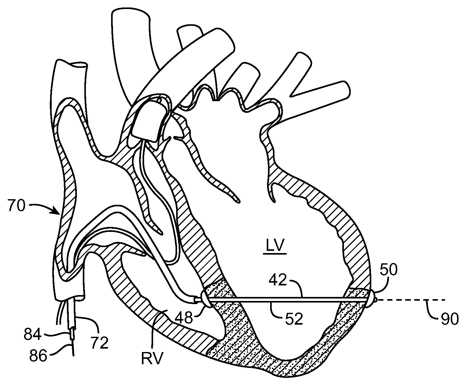
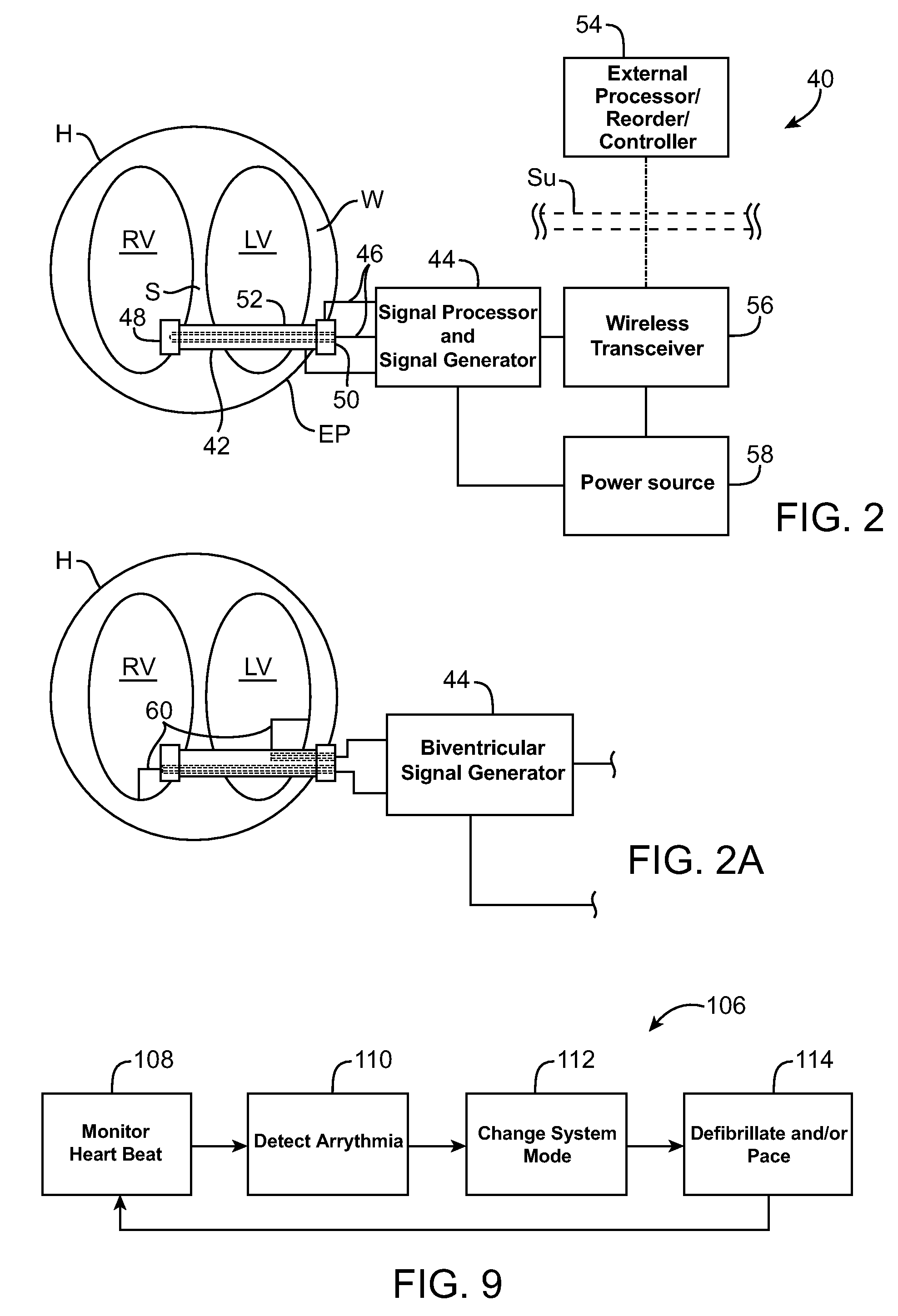
[0013]The present invention generally provides improved devices, systems, and methods for treating a diseased or at-risk heart of a patient. Embodiments of the invention may make use of structures which decrease or limit a size of a chamber of the heart, such as by deploying a tensile member to bring two walls of the heart (one of which is usually, but not necessarily the interventricular septum) into contact, thus diminishing a circumference of the chamber. In addition to limiting a dimension across the chamber, the implant may include an electrode or other structure for applying signals (often as electrical potential or voltage, current, or the like) to one or both ventricles of the heart, such as for defibrillating the heart, pacing the heart, or the like. In many embodiments, the implant may sense motion, intercavity pressure, oxygen saturation, flow, activation potentials, or other measurements of function or beating of the heart, optionally using the same electrodes and / or other sensor surface(s) of the implanted device. Exemplary embodiments of the implant may be included within a hardwired and / or wireless telemetry and control system, allowing the implant to not only treat congestive heart failure and monitor the results of the treatment, but to apply appropriate electrical stimulation based on monitored activity of the treated heart.
[0017]First and second anchors may affix the tensile member to the septum and wall of the heart, thus effectively sealing the septum around signals that are transmitted transceptally. Defibrillation signals may be passed from the implant to the heart by using an electrode surface of at least one of the anchors, such as through use of an electrode surface along the anchors or the like. Where the implant extends through the wall, the second anchor may engage and apply heart defibrillation voltage to an epicardial surface of the wall. In some embodiments, a lead for pacing or sensing contractions may be deployed at a location which is separated from that of the anchors. For example, the implant may optionally help measure heart contractile signals along an epicardial surface of the wall or from the septum using such leads.

Problems solved by technology

However, in most cases congestive heart failure may be triggered by a heart attack or myocardial infarction.
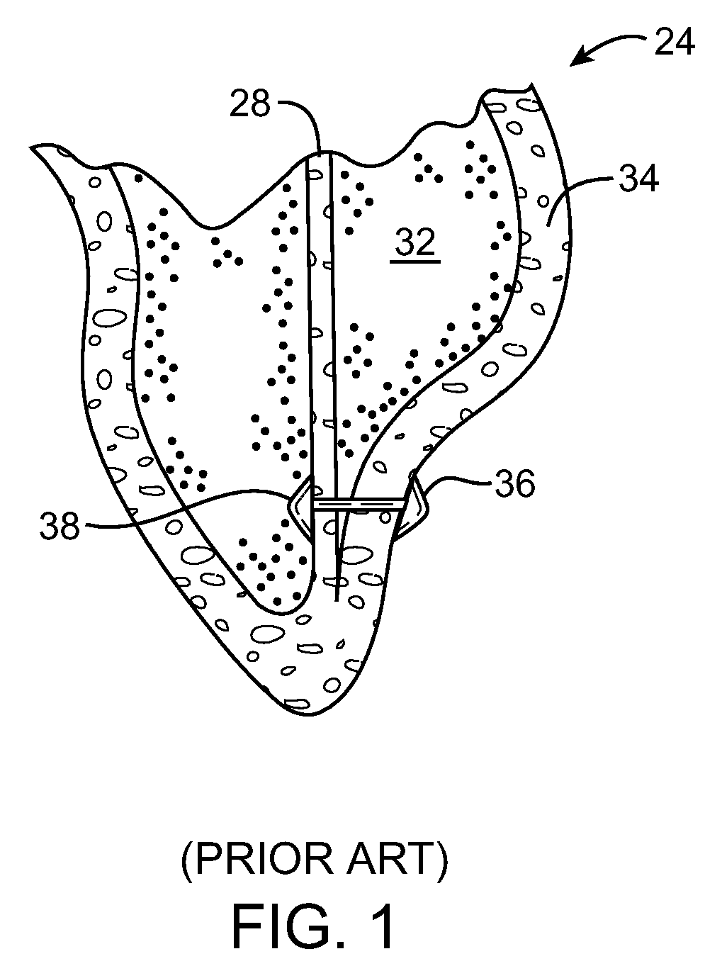
Heart attacks can cause scar tissue that interferes with the heart muscle's healthy function, and that scar tissue can progressively replace more and more of the heart tissue.
People with heart failure may have difficulty exerting themselves, often becoming short of breath, tired, and the like.
As blood flow out of the heart slows, blood returning to the heart through the vascular system decreases, causing congestion in the tissues.
Fluid may also collect in the lungs, interfering with breathing (especially when lying down).
Congestive heart failure may also decrease the ability of the kidneys to remove sodium and water, and the fluid buildup may be sufficient to cause substantial weight gain.
With progression of the disease, this destructive sequence of events can cause the eventual failure of the remaining functional heart muscle.
These surgical therapies can be at least partially effective, but typically involve substantial patient trauma.
With congestive heart failure, the left ventricle often dilates or increases in size.
This can result in a significant increase in wall tension and stress.

Method used


Image

  • Signal Transmitting and Lesion Excluding Heart Implants for Pacing Defibrillating and/or Sensing of Heart Beat
  • Signal Transmitting and Lesion Excluding Heart Implants for Pacing Defibrillating and/or Sensing of Heart Beat
  • Signal Transmitting and Lesion Excluding Heart Implants for Pacing Defibrillating and/or Sensing of Heart Beat

Examples


Embodiment Construction

[0043]The present invention generally provides improved devices, systems, and methods for treatment of a heart. Embodiments of the invention may be particularly beneficial for treatment of congestive heart failure and other disease conditions of the heart. The invention may find uses as a prophylactic treatment, and / or may be included as at least a portion of a therapeutic intervention.

[0044]Myocardial infarction and the resultant scar formation is often the index event in the genesis of congestive heart failure. The presence of the scar may, if left untreated, lead to a compensatory neuro-hormonal response by the remaining, non-infarcted myocardium. The systems, methods, and devices described herein may be applied to inhibit, reverse, or avoid this response altogether, often halting a destructive sequence of events which could otherwise cause the eventual failure of the remaining functional heart muscle.

[0045]Embodiments of the present invention may build on known techniques for ex...


PUM


Abstract

Devices, systems, and methods for treating a heart of a patient may make use of structures which limit a size of a chamber of the heart, such as by deploying a tensile member to bring a wall of the heart toward (optionally into contact with) a septum of the heart. The implant may include an electrode or other structure for applying pacing signals to one or both ventricles of the heart, for defibrillating the heart, for sensing beating of the heart or the like. A wireless telemetry and control system may allowing the implant to treat congestive heart failure, monitor the results of the treatment, and apply appropriate electrical stimulation.

Description

CROSS-REFERENCES TO RELATED APPLICATIONS[0001]NOT APPLICABLESTATEMENT AS TO RIGHTS TO INVENTIONS MADE UNDER FEDERALLY SPONSORED RESEARCH OR DEVELOPMENT[0002]NOT APPLICABLEREFERENCE TO A “SEQUENCE LISTING,” A TABLE, OR A COMPUTER PROGRAM LISTING APPENDIX SUBMITTED ON A COMPACT DISK[0003]NOT APPLICABLEBACKGROUND OF THE INVENTION[0004]The present invention is generally directed to improved devices, systems, and methods for treatment of the heart. Exemplary embodiments provide implants and methods for alleviating congestive heart failure and other progressive diseases, for pacing (often biventricular pacing), for monitoring beating of the heart, and / or the like. Congestive heart failure may, for example, be treated using an implant which excludes scar tissue and limits a cross section across a ventricle, with the implant also being used to help in sensing the heart function and pacing or (as needed) defibrillating the heart.[0005]Congestive heart failure (sometimes referred to as “CHF” ...

Claims


Application Information

Patent Timeline
Patent Type & Authority Applications(United States)
IPC IPC(8): A61N1/05
CPCA61N1/3627A61N1/3956A61N1/3987A61B17/12122A61F2/2487A61N1/057A61B17/1215
Inventor ANNEST, LON S.BERTOLERO, ARTHUR A.SWANSON, DAVID K.
Owner BIOVENTRIX A CHF TECH
Learn More