
Battery integration and control in an auxiliary power unit powered by a solid oxide fuel cell system

a fuel cell and auxiliary power technology, applied in battery/fuel cell control arrangement, secondary cell servicing/maintenance, electrochemical generators, etc., can solve the problems of damage to the fuel cell stack and the inability to provide the required power

Inactive Publication Date: 2008-04-10
DELPHI TECH INC
View PDF7 Cites 32 Cited by
  • Summary
  • Abstract
  • Description
  • Claims
  • Application Information

AI Technical Summary

Benefits of technology

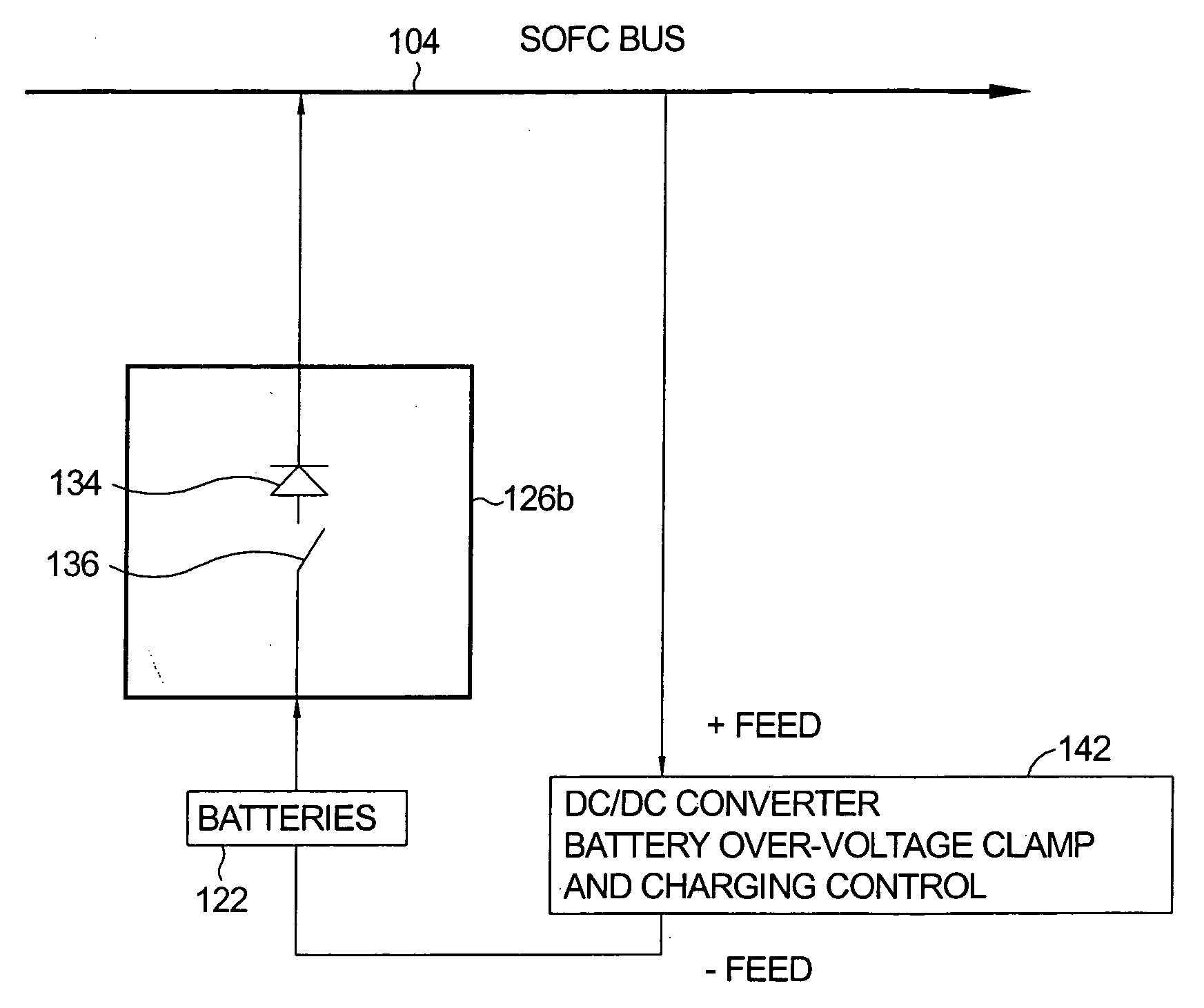
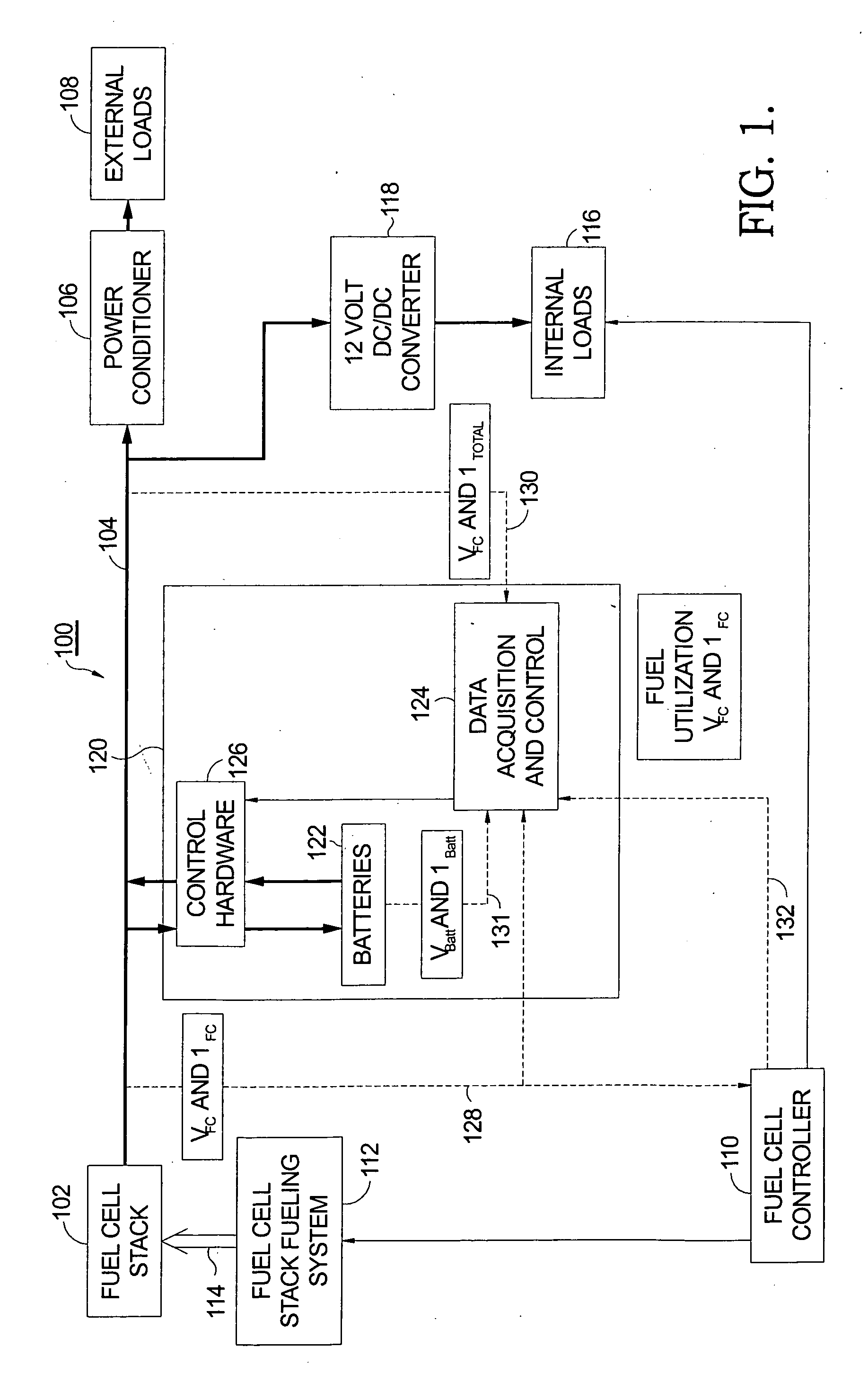
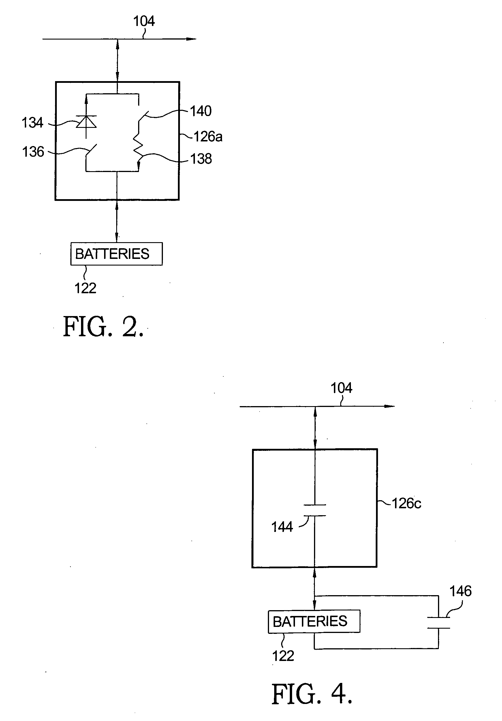
[0012]Briefly described, an auxiliary power unit (APU) providing electric power from a fuel cell stack at a nominal steady state output experiences an instantaneous voltage drop when maximum load is called for, which voltage drop can damage the fuel cell stack. Also, the required power cannot be provided for a short lag period during which the fuel cell fueling is ramped up. In the present invention, a battery source is provided in parallel with the fuel cell stack to meet the burst power demand during the fuel cell ramp-up lag. Various control mechanisms are disclosed to assure that the necessary power is provided while also protecting both the fuel cell stack and the battery from damaging voltage levels. A vehicular application with a shared vehicle battery is also disclosed.

Problems solved by technology

Briefly described, an auxiliary power unit (APU) providing electric power from a fuel cell stack at a nominal steady state output experiences an instantaneous voltage drop when maximum load is called for, which voltage drop can damage the fuel cell stack.
Also, the required power cannot be provided for a short lag period during which the fuel cell fueling is ramped up.

Method used


Image

  • Battery integration and control in an auxiliary power unit powered by a solid oxide fuel cell system
  • Battery integration and control in an auxiliary power unit powered by a solid oxide fuel cell system
  • Battery integration and control in an auxiliary power unit powered by a solid oxide fuel cell system

Examples


Embodiment Construction

[0021]As noted above, in the prior art of SOFC APU systems, the electrical load (internal parasitic plus external) on the APU must be carefully controlled. The principal reason why this is so is that the fuel cell stack tends to run above a certain voltage per cell, for too low a cell voltage can cause very high cell temperatures resulting in cell failure. The stack also tends to run below a ceiling value of fuel utilization.

[0022]A critical control challenge occurs in an APU when the electrical load transitions from idle to full load. Sensing this additional load by a system controller causes an increase in fuel flow; however, an inherent lag exists in providing increased flow of anode and cathode gases. In a known hydrocarbon reformer system for feeding fuel gas to the fuel cell stack, this time lag is approximately two seconds. As a result, the stack voltage per cell instantaneously falls, and can fall below a desired voltage floor. Moreover, the system will likely fall to a volt...


PUM

PropertyMeasurementUnit
time lagaaaaaaaaaa
voltageaaaaaaaaaa
voltagesaaaaaaaaaa

Abstract

An auxiliary power system providing electric power from a fuel cell stack at a nominal steady state output experiences an instantaneous voltage drop when maximum load is called for, which voltage drop can damage the fuel cell stack. Also, the required power increase cannot be provided for a short lag period during which the fuel cell fueling is ramped up. In the present invention, an electricity storage device, such as a battery, is provided in parallel with the fuel cell stack to meet the burst power demand during the fuel cell ramp-up lag. Various alternative control mechanisms are disclosed to assure that the necessary power is provided while also protecting both the fuel cell stack and the battery from damaging voltage swings. A vehicular application with a shared vehicle battery is also disclosed.

Description

TECHNICAL FIELD[0001]The present invention relates to fuel cell systems for providing electric power; more particularly, to solid oxide fuel cell systems and devices for controlling their use in an auxiliary electric power unit; and most particularly, to method and apparatus for integration and control of a battery in an auxiliary power unit powered by a solid oxide fuel cell system.BACKGROUND OF THE INVENTION[0002]Fuel cell systems for converting hydrogen, carbon monoxide, and oxygen into carbon dioxide and water to generate electricity are well known. One such type of fuel cell system is known in the art as a solid oxide fuel cell (SOFC) system. A known use for an SOFC system is as an auxiliary power unit (APU) for providing supplemental electric power to an associated function having another, primary source of electric power.[0003]One example of an APU application is in a vehicle, which may be motively powered by an internal combustion engine, gas turbine engine, or electric moto...

Claims


Application Information

Patent Timeline
Patent Type & Authority Applications(United States)
IPC IPC(8): H01M16/00H01M8/12H01M8/04
CPCB60L11/1887Y02E60/525H01M8/04619H01M8/04753H01M8/0488H01M8/0494H01M8/04947H01M10/06H01M10/44H01M16/006H01M2008/1293H01M2250/20H02J7/1423H02J7/34H02J2001/004Y02T10/7016Y02T90/32Y02T90/34Y02E60/50H01M8/04589B60L58/40H02J2300/30Y02E60/10Y02T10/70Y02T90/40
Inventor MACBAIN, JOHN A.RAJASHEKARA, KAUSHIK
Owner DELPHI TECH INC
Learn More