Porous Honeycomb Filter

a honeycomb filter and porous technology, applied in the field of porous honeycomb filters, can solve the problems of degrading trapping efficiency, achieve the effect of balancing trapping efficiency, increasing pressure loss, and reducing trapping efficiency

Inactive Publication Date: 2008-04-24
NGK INSULATORS LTD
View PDF17 Cites 40 Cited by
  • Summary
  • Abstract
  • Description
  • Claims
  • Application Information

AI Technical Summary

Benefits of technology

[0021] The porous honeycomb filter is clogged with the catalyst carried by pores having a pore diameter of 15 μm or less, which is a cause for an increase in pressure loss. On the other hand, pores having a pore diameter of 40 μm or more cause a drop in trapping efficiency. In the honeycomb filter of the present invention, since the volume of the pores having a pore diameter of 15 μm or less is 0.07 cc / cc or less, and the volume of the pores having a pore diameter of 40 μm or more is 0.07 cc / cc or less, the pressure loss and the trapping efficiency can be balanced.
[0022] Moreover, in the honeycomb filter of the present invention, since both of the volumes of the pores having small and large pore diameters are defined by absolute values, the volumes of the pores having these diameters are not related to the total pore volume. Even when the total pore volume fluctuates, the volumes of the pores having these diameters do not fluctuate, and therefore the trapping efficiency of the filter as a whole does not drop.

Problems solved by technology

However, it has been found that a trapping efficiency of particulates sometimes drops when the pore diameter increases and that the trapping efficiency degrades especially in a case where the volume of pores having a diameter of 40 μm or more increases.

Method used


Image

  • Porous Honeycomb Filter
  • Porous Honeycomb Filter
  • Porous Honeycomb Filter

Examples


example 1

[0050] As a ceramic material, 75 mass % of silicon carbide powder and 25 mass % of metal silicon powder were used. To 100 parts by mass of ceramic material, 10 parts by mass of crosslinked starch having an average particle diameter of 45 μm were added. Furthermore, methyl cellulose, hydroxypropoxyl methyl cellulose, surfactant, and water were added and mixed, and a plastic clay was prepared by a vacuum clay kneader.

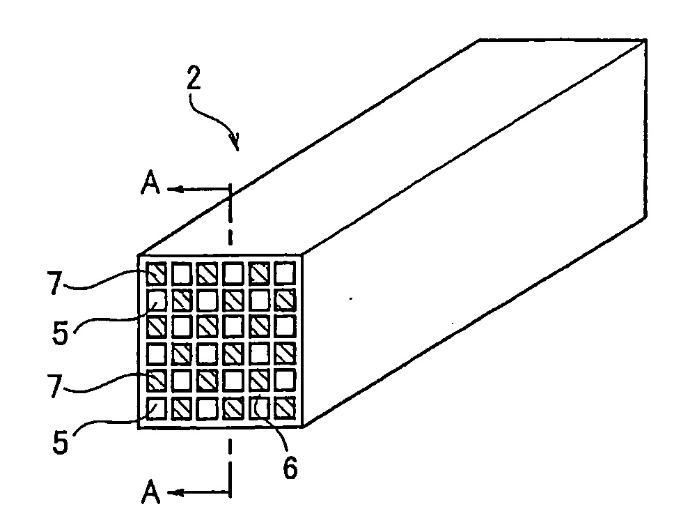
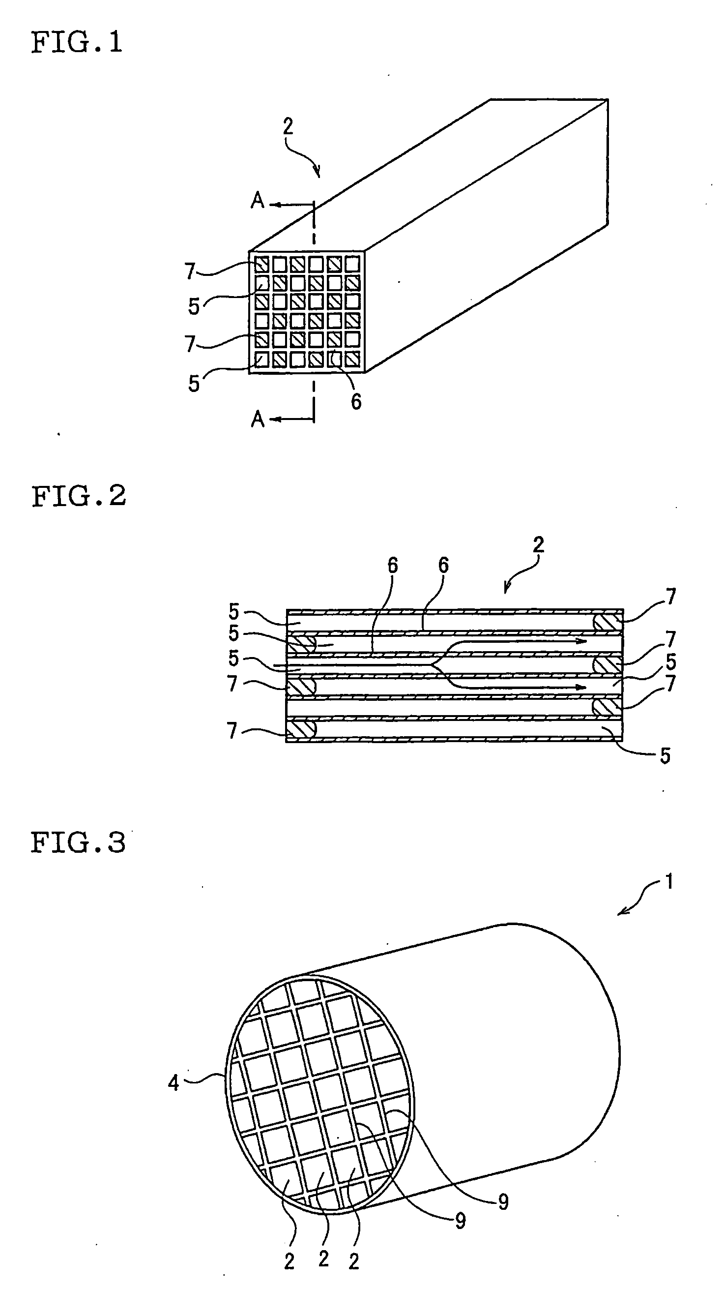
[0051] This clay was extruded, and a ceramic molded article was obtained. This ceramic molded article was dried with microwave and hot air, and thereafter degreased at 400° C. in the atmosphere. Thereafter, the article was fired at about 1450° C. in an argon inactive atmosphere, and there was obtained a porous honeycomb filter made of a metal silicon-silicon carbide composite material and having: a partition wall thickness of 300 μm; a cell density of 46.5 cells / cm2 (300 cells / square inch); a square section whose side was 35 mm; and a length of 152 mm.

example 2

[0052] A porous honeycomb filter having a honeycomb structure was prepared by a similar method by use of a raw material similar to that of Example 1 except that an amount of crosslinked starch powder to be added was set to 15 parts by mass.

example 3

[0053] A porous honeycomb filter was prepared by a similar method by use of a raw material similar to that of Example 1 except that 70 mass % of silicon carbide powder and 30 mass % of metal silicon powder were used as a ceramic material, a partition wall thickness was set to 381 μm, and a cell density was set to 31.0 cells / cm2 (200 cells / square inch).


PUM

PropertyMeasurementUnit
pore diameteraaaaaaaaaa
porosityaaaaaaaaaa

Abstract

There is disclosed a porous honeycomb filter whose trapping efficiency does not drop even when a porosity fluctuates and which is capable of balancing the trapping efficiency and a pressure loss. The porous honeycomb filter is a filter whose pore distribution has been controlled. A volume of pores having a pore diameter of 15 μm or less is 0.07 cc/cc or less, and a volume of pores having a pore diameter of 40 μm or more is 0.07 cc/cc or less.

Description

TECHNICAL FIELD [0001] The present invention relates to a porous honeycomb filter, more particularly to a porous honeycomb filter capable of balancing a trapping efficiency of particulates and a pressure loss. BACKGROUND ART [0002] As a method of trapping and removing particulates discharged from a diesel engine, a method of incorporating a diesel particulate filter (DPF) into an exhaust system of the diesel engine is put to practical use. This DPF is a porous honeycomb filter having a predetermined shape, or is prepared by bonding a plurality of porous honeycomb filters. [0003]FIGS. 1 and 2 show a porous honeycomb filter 2 for use in the DPF. This porous honeycomb filter 2 is molded into a cylindrical shape having a square section, and has therein a large number of circulation holes 5 defined by partition walls 6. Each partition wall 6 has a porous structure in which a large number of pores are distributed, and accordingly a gas can pass through the partition walls 6. [0004] The ci...

Claims


Application Information

Patent Timeline
Patent Type & Authority Applications(United States)
IPC IPC(8): B01D39/00
CPCC04B38/0006C04B35/584C04B2111/0081C04B2111/00793C04B35/565C04B35/195C04B35/185B01J35/04B01D2275/30C04B35/18C04B38/0054C04B38/0074C04B38/068C04B35/56C04B35/58B01D39/00
Inventor OTSUKA, AIKOICHIKAWA, SHUICHI
Owner NGK INSULATORS LTD
Why Eureka
Try Eureka