Production of Ferro-Alloys
a technology of ferro-alloys and alloys, which is applied in the direction of manufacturing tools, electric furnaces, furnaces, etc., can solve the problems of slag foaming, contamination, pollution, etc., and interfere with the production of ferro-alloys,
- Summary
- Abstract
- Description
- Claims
- Application Information
AI Technical Summary
Benefits of technology
Problems solved by technology
Method used
Image

Examples
example 1
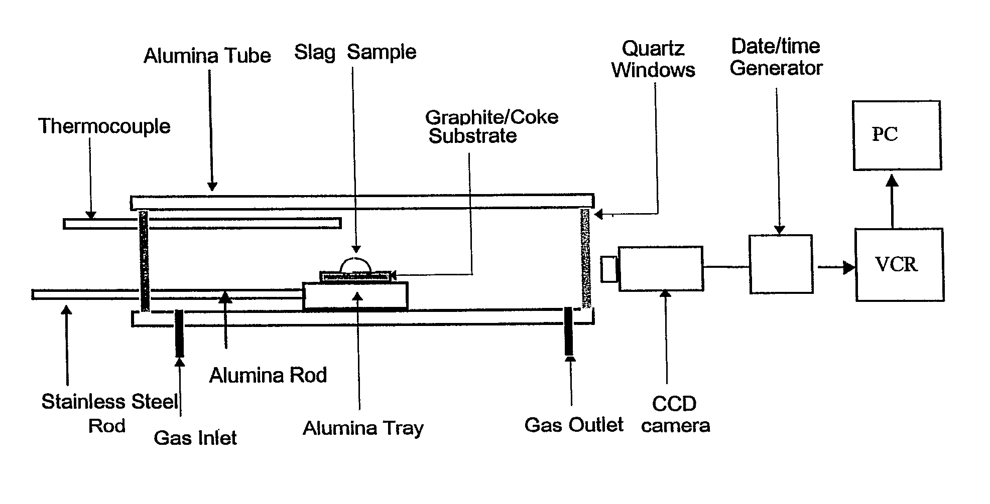
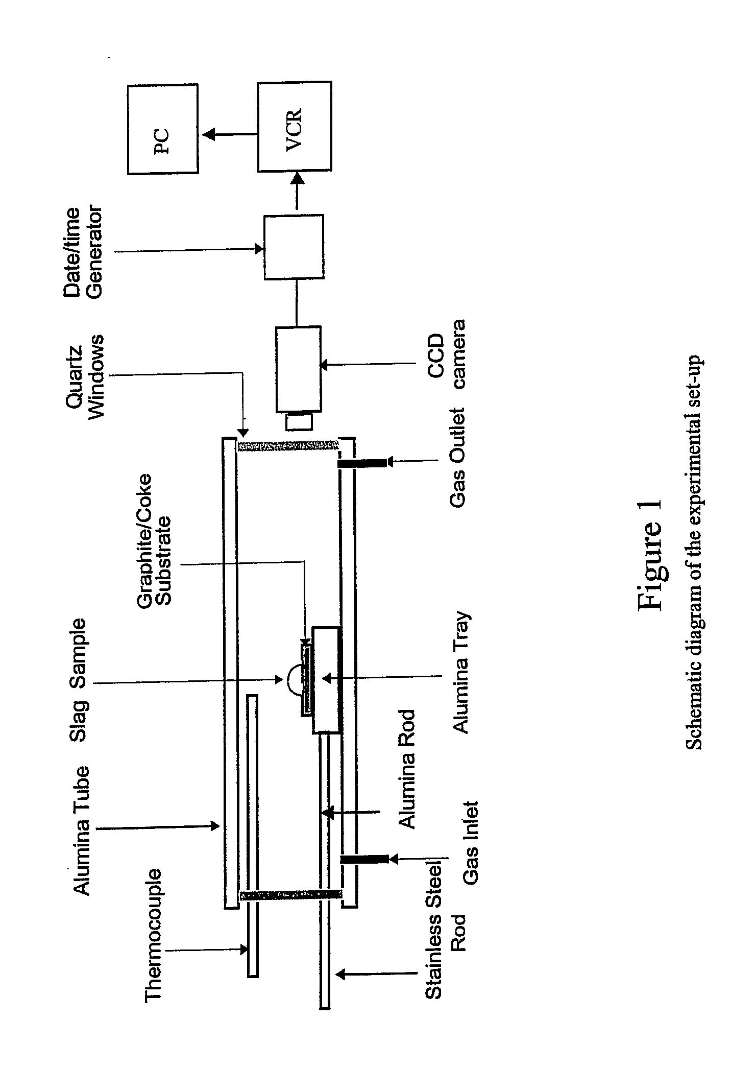
[0063]To investigate slag foaming, slag / carbon interactions were first investigated in a laboratory scale, horizontal tube resistance furnace using the sessile drop approach. A schematic diagram of the experimental set up is shown in FIG. 1. The weight of the slag used was ˜0.20 g. Initially, the sample was held on a specimen holder, which could be pushed to the centre of the hot zone in the furnace with the help of a stainless steel rod.
[0064]The slag / carbon assembly was held in the cold zone of the furnace until the desired temperature (1550° C.) was attained and equilibrated in the hot zone of the furnace. The assembly was inserted into the hot zone at the desired temperature of study. This eliminated any reaction that could occur at lower temperatures and possibly influence the phenomena to be studied at the temperature of interest. The furnace tube was purged with argon throughout the duration of the experiment. The argon flow rate was controlled by a mass flow meter.
[0065]The ...
example 2
[0072]An analysis of plant operating data from an operating EAF showed that increasing levels of coke injection resulted in increased consumption of oxygen, although they did not yield any well-defined pattern in power consumption per ton of steel charged.
[0073]The operating EAF used two different forms of carbon in its operation. Along with coke containing˜90% C, it used a few tons of flat iron containing 4% C. Carbon present in the flat iron was already dissolved when the flat iron melted, whereas carbon present in the coke was present in a solid state.
[0074]The form of carbon (solute or solid carbon) was observed to have a significant effect on average power consumed / ton of steel. With an increased amount of flat iron charged (equivalent to higher levels of solute carbon) there was a significant reduction in power consumption. This trend was interpreted in terms of the role played by the carbonaceous material and indicated that an increase in slag foaming lead to a decrease in po...
example 3
[0080]The inventors now tested the addition of waste plastics to an EAF process in place of at least some of the traditional source of carbon (eg. coke). The following raw materials were assembled to simulate the raw materials fed to an EAF.
Raw Materials
[0081]The following carbonaceous materials, plastics and slag were employed to conduct comparative slag foaming experiments.
Carbonaceous materials: graphite; coke; residue generated from a mixture (1:1) of graphite and plastic (the XRD spectrum of this residue is provided in FIG. 6). The ratio of 1:1 may vary from furnace to furnace.
Plastic material: Linear Low Density Polyethylene (LLDPE) was obtained to represent the major constituent of plastic waste. Particle sizes of polyethylene samples used were less than 100 micrometers.
Slag: The following slag composition (% wt) was prepared: 30.48% CaO; 11.72% MgO; 13.34% SiO2; 5.24% Al2O3; 33.33%, Fe2O3; 5.24% MnO.
[0082]A substrate of carbonate material powders were prepared by hydraulic p...
PUM
| Property | Measurement | Unit |
|---|---|---|
| Temperature | aaaaa | aaaaa |
| Fraction | aaaaa | aaaaa |
| Fraction | aaaaa | aaaaa |
Abstract
Description
Claims
Application Information
 - R&D
- Intellectual Property
- Life Sciences
- Materials
- Tech Scout
- Unparalleled Data Quality
- Higher Quality Content
- 60% Fewer Hallucinations
Browse by: Latest US Patents, China's latest patents, Technical Efficacy Thesaurus, Application Domain, Technology Topic, Popular Technical Reports.
© 2025 PatSnap. All rights reserved.Legal|Privacy policy|Modern Slavery Act Transparency Statement|Sitemap|About US| Contact US: help@patsnap.com