Light modulating material

a technology light transmittance, which is applied in the field can solve the problems of reducing the light transmittance deteriorating coloring properties, and the inability of light modulating material to be in a transparent sta

Inactive Publication Date: 2008-04-24
FUJIFILM CORP
View PDF3 Cites 55 Cited by
  • Summary
  • Abstract
  • Description
  • Claims
  • Application Information

AI Technical Summary

Benefits of technology

[0014]In accordance with the above circumstances, the present invention provides a light modulating material capable of supplying a predetermined light modulating property over a long period of time regardless of the conditions of incident light.
[0027]According to the invention, a light modulating material capable of supplying a predetermined light modulating property over a long period of time regardless of an incident light condition can be provided.

Problems solved by technology

However, this method is problematic in that the walls of the capsules may be stained with the dichroic dyes, or the voltage response may become nonexistent because the dichroic dyes have aligned along the polymer film too easily, resulting in a reduction of light transmittance of the light modulating material when in a transparent state.
However, this method is problematic in that the dye decomposes due to irradiation with UV light, or due to the presence of the polymerization initiator, resulting in deterioration in coloring properties.
Therefore, it is impossible for the light modulating material to be in a transparent state when voltage cannot be applied thereto due to wiring problems, a discharged battery, or the like.
However, these methods are not widely used because the light modulating materials employing the methods are white when they scatter light, and have poor light-shading properties.
Thus, this system has a poor shading property between these states.

Method used


Image

  • Light modulating material
  • Light modulating material
  • Light modulating material

Examples


example 1

Production of Second Liquid Crystal Layer

[0208]A vertical alignment film: SE-1211 (trade name, manufactured by Nissan Chemical Industries, Ltd.) was applied to each of ITO substrates (manufactured by EHC: 100Ω / □) and the resultants were then sintered. The resultant substrates were attached at an interval of 8 μm to produce a liquid crystal cell.

[0209]A liquid crystal composition precursor was made by mixing MLC-6610 (trade name, manufactured by Merck & Co., Inc., Δ∈: −3.1, Δn: 0.0996, nematic liquid crystal) used as a liquid crystal compound, with 5% by mass of A-BPE-4 (trade name, manufactured by Shin-Nakamura Chemical Co., Ltd.) used as a monomer and 0.4% by mass of DAROCUR®1173 (manufactured by Ciba Specialty Chemicals) used as a photopolymerization initiator. The liquid crystal composition precursor was injected into the liquid crystal cell, light was radiated thereonto by using a UV lamp (emission wavelength of 360 nm and power of 36 W) for 10 min, and heating was performed in ...

example 2

Production of Second Liquid Crystal Layer

[0217]SiO2 was applied on a PEN film (125Ω / □) provided with ITO to provide a film having a thickness of 3000 Å by ion plating. A mask was then applied on an area to which a sealing agent was applied and an area to which an ejection electrode was applied on the film by using polyimide tape. The film was immersed in a solution obtained by dissolving n-octadecyltrimethoxysilane in a solvent mixture of 95% by mass of isopropyl alcohol and 5% by mass of pure water, and then heated in an oven at 80° C. for 10 min.

[0218]After the polyimide tape was removed, a solution produced by dissolving 2% by mass of 3-glycidoxypropyl methoxysilane (manufactured by Chisso Corporation) in ethanol was applied on the areas from which the tape was removed, and the film was dried in an oven at 80° C. Next, the film was immersed in pure water and subsequently isopropyl alcohol in this order, subjected to ultrasonic wave washing, and dried.

[0219]After spacers each havi...


PUM

PropertyMeasurementUnit
light transmittanceaaaaaaaaaa
thicknessaaaaaaaaaa

Abstract

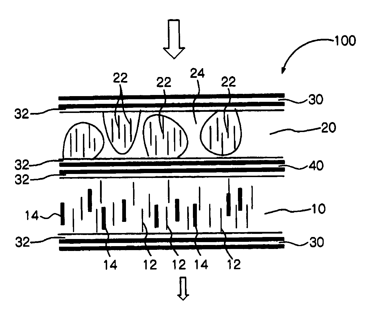
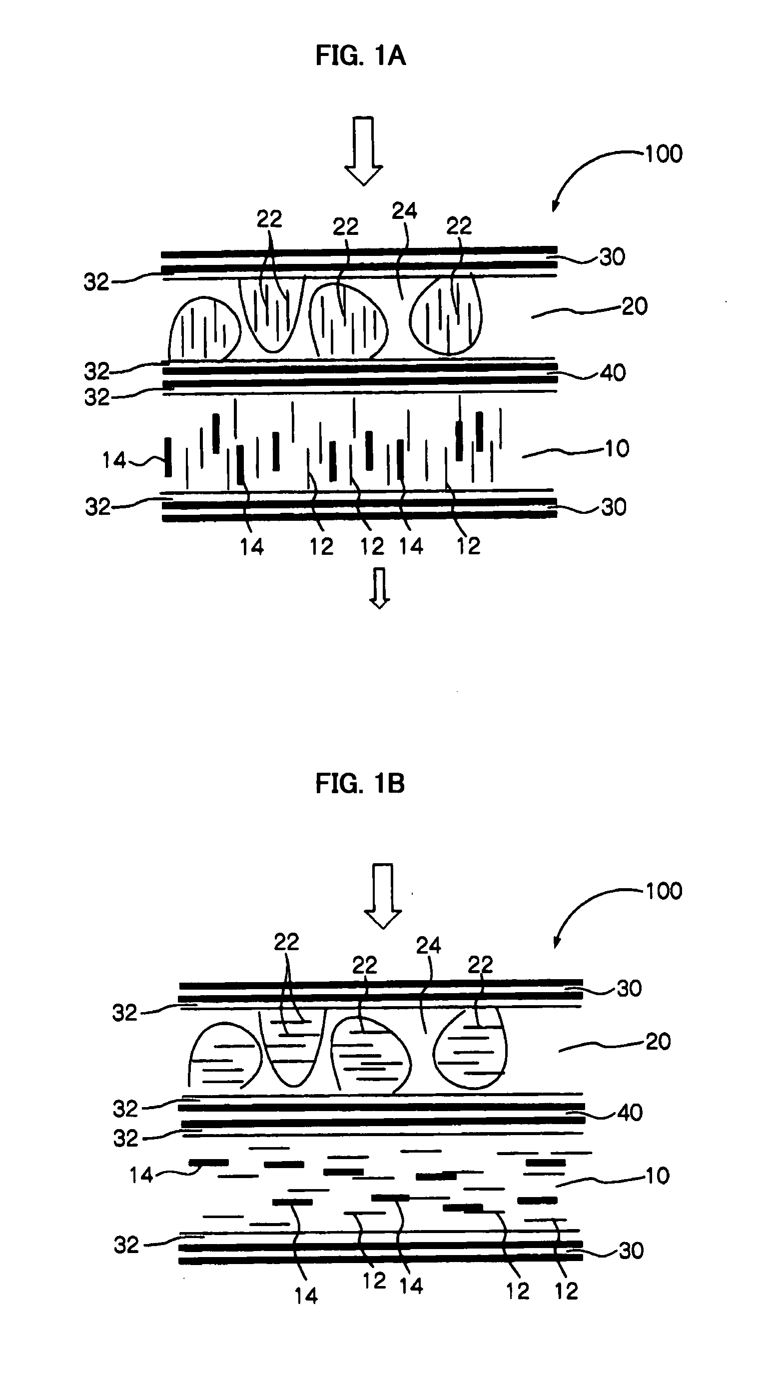
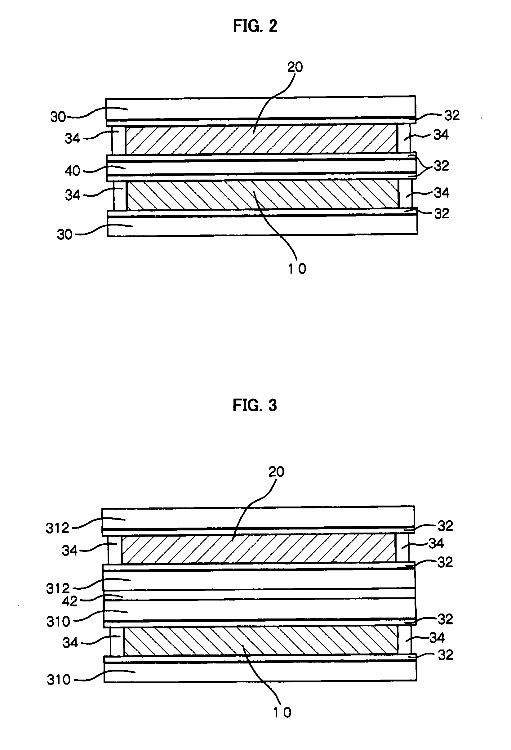
The invention provides a light modulating material capable of supplying a predetermined light modulating property over a long period of time regardless of an incident light condition. The light modulating material includes at least: a first liquid crystal layer which has at least a dichroic dye and changes from a colorless transparency state to a colored transparency state when voltage is applied thereto; and a second liquid crystal layer which changes from a colorless transparency state to a white light-scattering state when voltage is applied thereto. The second liquid crystal layer is provided closer to a surface of the light modulating material on which light is incident compared to the first liquid crystal layer.

Description

CROSS-REFERENCE TO RELATED APPLICATION[0001]This application claims priority under 35 USC 119 from Japanese Patent Application No. 2006-285186, the disclosure of which is incorporated by reference herein.BACKGROUND OF THE INVENTION[0002]1. Field of the Invention[0003]The present invention relates to a light modulating material.[0004]2. Description of the Related Art[0005]In light modulating materials using liquid crystal, switching between a scattered (light-shading) state and a transparent state is performed by the following methods.[0006]For example, a method in which microcapsules containing liquid crystal are dispersed in a polymer has been suggested (see e.g. “Development of Chromic materials”, edited by Kunihiro Ichimura, CMC Publishing, pp. 226-236, 2000). According to this method, when voltage is not applied, liquid crystal molecules align randomly and light scatters due to diffused reflection resulting from a difference in the refractive indices of the liquid crystal molecu...

Claims


Application Information

Patent Timeline
Patent Type & Authority Applications(United States)
IPC IPC(8): G02F1/1347
CPCG02F1/13475
Inventor HAYASHI, NAOYUKITAKAKU, KOJIKATO, TAKASHI
Owner FUJIFILM CORP
Why Eureka
Try Eureka