
Negative electrode and non-aqueous electrolyte secondary battery using the same

a secondary battery and negative electrode technology, applied in the field of negative electrodes for non-aqueous electrolyte secondary batteries, can solve the problems of reducing the charge/discharge cycle performance of batteries, affecting so as to achieve the effect of improving the charge/discharge cycle performan

Inactive Publication Date: 2008-04-24
PANASONIC CORP
View PDF7 Cites 160 Cited by
  • Summary
  • Abstract
  • Description
  • Claims
  • Application Information

AI Technical Summary

Benefits of technology

[0013] The present inventors have conducted detailed studies on a negative electrode using an active material containing at least one of a metal element and a semi-metal element capable of reversibly absorbing and desorbing lithium aiming at improvement of the charge / discharge cycle performance of a non-aqueous electrolyte secondary battery.
[0014] As a result, they have found that excellent charge / discharge cycle performance can be achieved when the negative electrode comprises a conductive porous substrate, and a conductive material and an active material filled in pores of the porous substrate, and the active material contains at least one of a metal element and a semi-metal element capable of reversibly absorbing and desorbing lithium.
[0028] The present invention makes it possible to maintain uniform and stable current collection properties of a negative electrode in charge / discharge and provide excellent charge / discharge cycle performance. Specifically, since an active material is contained in a porous substrate, generation of cracks in a negative electrode or falling off of the active material from the negative electrode found in conventional negative electrodes having a negative electrode mixture layer can be suppressed even when volume change of active material particles is large in charge / discharge, making it possible to maintain the form of the negative electrode. Further, use of a conductive material having a diameter smaller than the average pore size of a porous substrate makes it possible to maintain a good current collection network among active material particles.

Problems solved by technology

However, using a material containing Si for a negative electrode often causes decrease in charge / discharge cycle performance of batteries.
However, in the methods of Japanese Laid-open Patent Publication Nos. 2004-103340, 2004-220910 and 2001-196064, suppressing expansion and shrinkage of a negative electrode in charge / discharge is difficult, and cracks may be generated in the negative electrode or the active material may fall off from the negative electrode.
However, since Si has a rate of expansion about four times higher than that of graphite when the battery is charged, even if current collection properties of active material particles near the foam metal can be ensured, current collection properties among active material particles may be deteriorated due to shrinkage of active material particles when the battery is discharged.
Also, since a negative electrode generally comprises a porous mixture layer containing an active material, a conductive material and a binder, expansion and shrinkage of the negative electrode often occur unevenly.
Large and uneven volume change in a negative electrode results in generation of cracks in the mixture layer or falling off of the active material from the mixture layer, causing current concentration in the negative electrode and often causing uneven charge / discharge reaction.
This generates heavily charged regions and lightly charged regions in the negative electrode, often causing deterioration of negative electrode properties.
In addition, large volume change due to charge / discharge destroys a current collection network among active material particles and active material particles not contributing to charge / discharge reaction are increased, easily resulting in deterioration of negative electrode properties.

Method used


Image

  • Negative electrode and non-aqueous electrolyte secondary battery using the same
  • Negative electrode and non-aqueous electrolyte secondary battery using the same

Examples


example 1

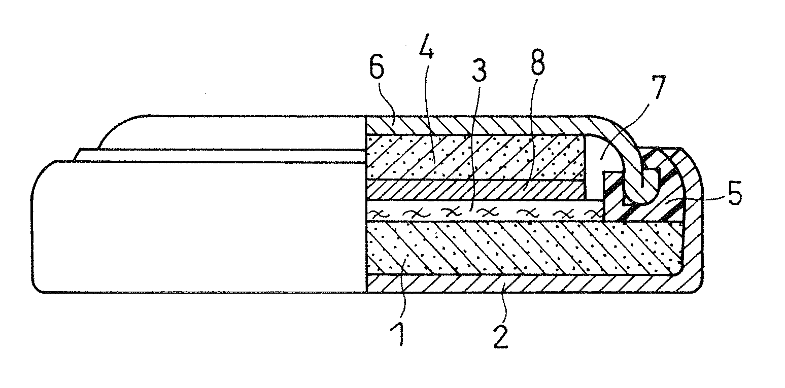
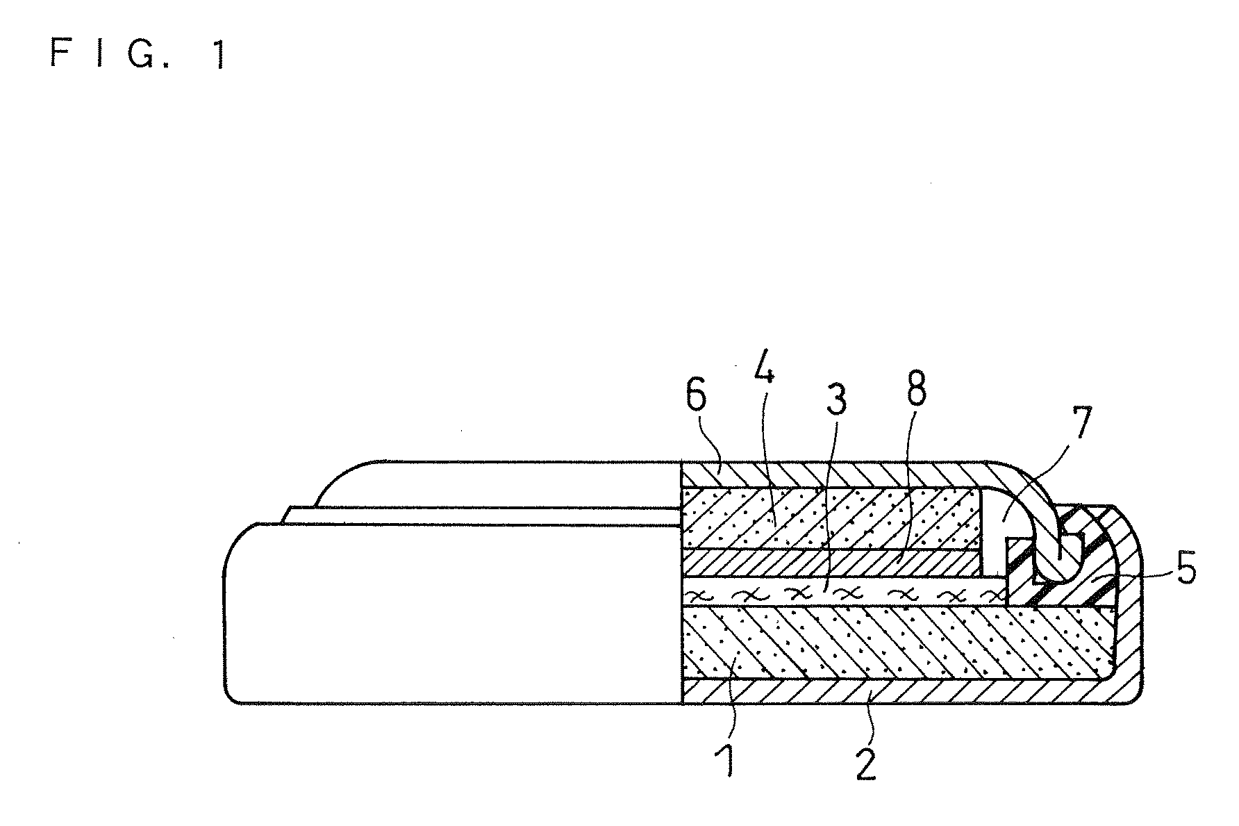
[0101] A coin type battery shown in FIG. 1, which is the non-aqueous electrolyte secondary battery of the present invention, was prepared by the following procedure. FIG. 1 is a front view of the coin type battery with a portion shown in a cross-section.

(1) Preparation of Negative Electrode Active Material

[0102] Ti powder (purity: 99.9%, particle size: 100 to 150 μm) and Si powder (purity: 99.9%, average particle size: 3 μm) were mixed so that the resulting alloy was composed of a TiSi2 phase (B phase) and a Si phase (A phase) and the Si phase content in the alloy was 20 parts by weight per 100 parts by weight of the total of the Si phase and the TiSi2 phase.

[0103] 3.5 kg of the mixed powder prepared above was put in the container of a vibrating mill (made by CHUO KAKOHKI CO., LTD., Model FV-20). Further, stainless steel balls (diameter: 2 cm) were put in the container so that the balls account for 70% by volume of the container volume. After evacuating the container, argon gas ...

example 2

[0115] A porous substrate was prepared by rolling a felt available from Kureha Corporation (product name: KURECA felt) so that the felt had a thickness of 300 μm and a porosity of 20%. The porous substrate made of the felt had an average pore size of about 50 μm. A battery was prepared in the same manner as in Example 1 using the porous substrate.

example 3

[0116] A porous substrate was prepared by rolling a paper available from TORAY INDUSTRIES, INC (product name: Carbon Paper) so that the paper had a thickness of 300 μm and a porosity of 20%. The porous substrate made of the paper had an average pore size of about 50 μm. A battery was prepared in the same manner as in Example 1 using the porous substrate.


PUM


Abstract

The negative electrode for a non-aqueous electrolyte secondary battery of the present invention includes a conductive porous substrate, and a conductive material and an active material filled in pores of the porous substrate. The active material contains at least one of a metal element and a semi-metal element capable of reversibly absorbing and desorbing lithium.

Description

FIELD OF THE INVENTION [0001] The present invention relates to a non-aqueous electrolyte secondary battery and, in particular, to an improved negative electrode for a non-aqueous electrolyte secondary battery. BACKGROUND OF THE INVENTION [0002] Conventionally, many studies have been done on non-aqueous electrolyte secondary batteries with high voltage and high energy density. For positive electrodes of non-aqueous electrolyte secondary batteries, transition metal oxides or transition metal chalcogen compounds are used. For example, LiMn2O4, LiCoO2, LiNiO2, V2O5, Cr2O5, MnO2, TiS2 and MoS2 are used. These compounds have a layered or tunnel crystal structure. Accordingly, the compounds are capable of absorbing and desorbing lithium ions. For negative electrodes, carbon materials capable of reversibly absorbing and desorbing lithium, such as graphite, for example, are used. Use of carbon materials makes it possible to prepare lithium ion batteries having excellent cycle life and safety...

Claims


Application Information

Patent Timeline
IPC IPC(8): H01M4/38H01M4/48H01M4/02H01M4/13H01M4/134H01M4/36H01M4/62H01M4/66H01M4/80H01M10/05
CPCH01M4/131H01M4/134H01M4/38H01M4/485H01M4/505Y02E60/122H01M4/80H01M4/801H01M4/808H01M10/0525H01M4/625H01M4/386H01M4/387Y02E60/10
Inventor BITO, YASUHIKOSANO, YOUKOYAMAMOTO, TERUAKI
Owner PANASONIC CORP
Learn More