Panel smoothing process and apparatus for forming a smooth continuous surface on fiber-reinforced structural cement panels
a technology of fiber reinforced structural cement and smoothing process, which is applied in the direction of surface layering apparatus, sustainable waste treatment, manufacturing tools, etc., can solve the problems of insufficient structural strength, and achieve the effect of removing pock marks or grooves
- Summary
- Abstract
- Description
- Claims
- Application Information
AI Technical Summary
Benefits of technology
Problems solved by technology
Method used
Image
Examples
second embodiment
of a Production Line
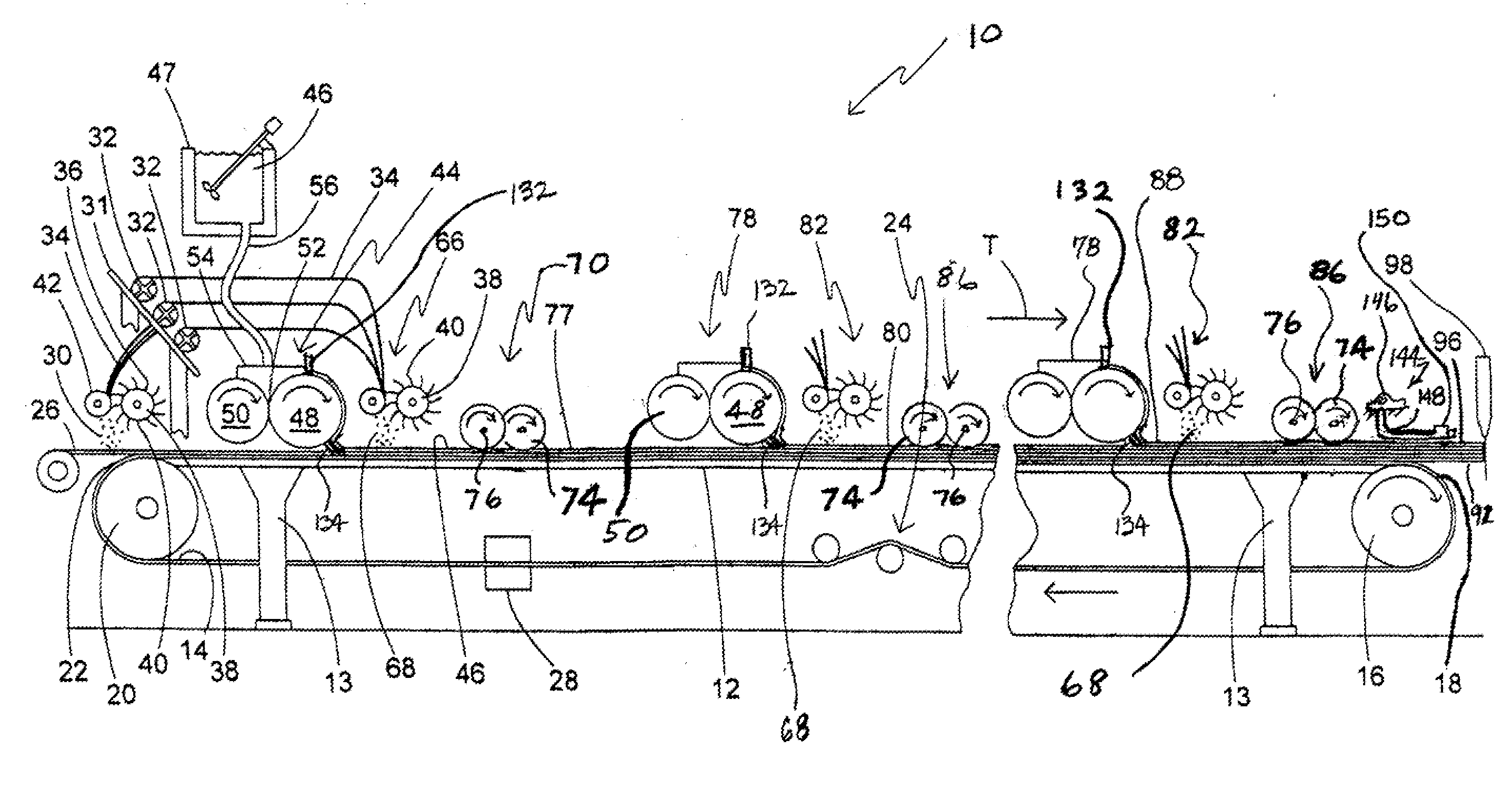
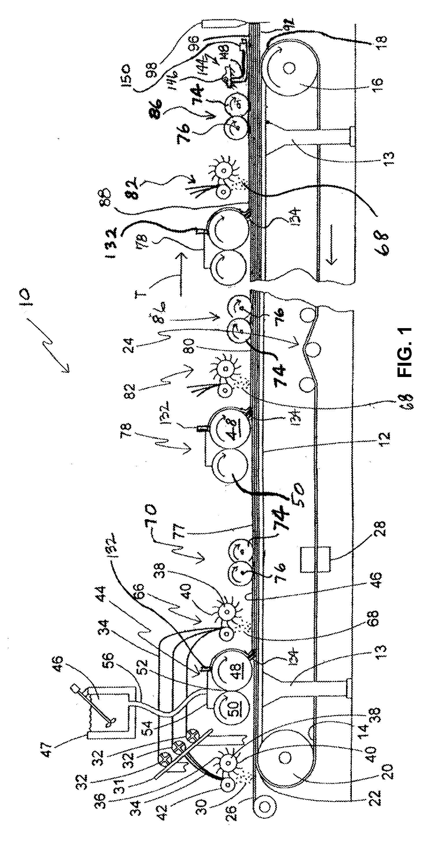
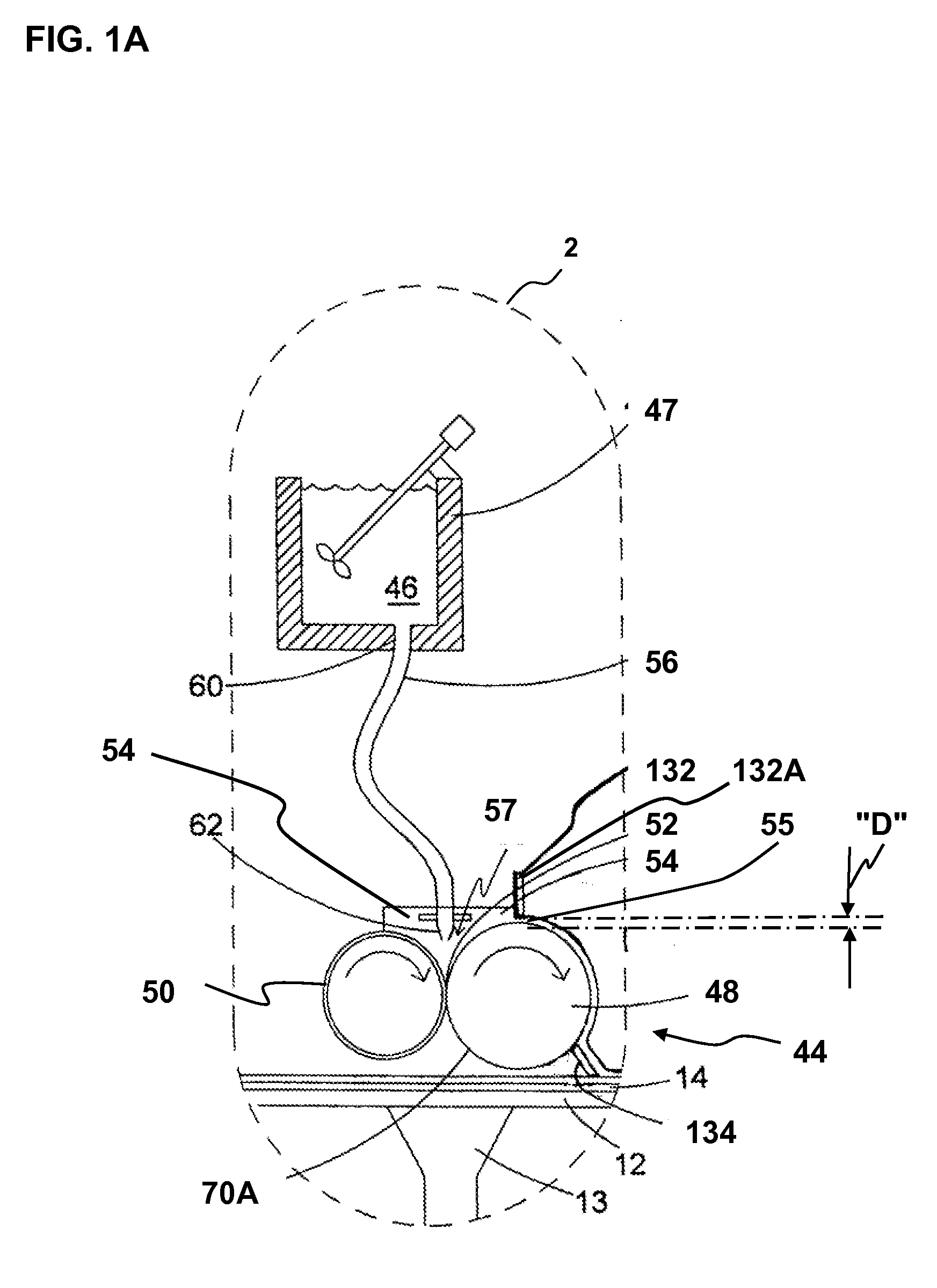
[0149]The incorporation of a volume fraction of loose fibers distributed throughout the slurry 46 is an important factor in obtaining desired panel strength. Thus, improved efficiency in incorporating such fibers is desirable. It is believed the system depicted in FIGS. 1-5 in some cases requires excessive numbers of slurry layers to obtain an SCP panel having sufficient fiber volume fraction.
[0150]Accordingly, an alternate SCP panel production line or system is illustrated in FIG. 6 and is generally designated 130 for producing high-performance, fiber reinforced SCP panels incorporating a relatively high volume of fibers per slurry layer. In many cases, increased levels of fibers per panel are obtained using this system. While the system of FIGS. 1-5 discloses depositing a single discrete layer of fibers into each subsequent discrete layer of slurry deposited after the initial layer, the production line 130 includes a method of building up multiple discrete rein...
example 1
[0214]Referring now to FIG. 1C, a fragment of the SCP panel 92 made from fibers and a slurry. The cements portion of the slurry comprises 65 wt. % Calcium sulfate alpha hemihydrate, 22 wt. % Type III Portland cement, 12 wt. % Silica Fume, and 1 wt. % hydrated lime. The liquid portion of the slurry comprises 99.19 wt. % water and 0.81 wt. % ADVACAST superplasticizer by W.R. Grace and Co. The liquid:cement weight ratio was 0.55 and the Aggregate (EXTENDOSPHERES SG microspheres):Cement weight ratio was 0.445.
[0215]The slurry was produced according to the present process, using the present system, and is shown to have four slurry layers, 77, 80, 88 and 90. This panel should be considered exemplary only in that a panel 92 produced under the present system may have one or more layers. By using the above mathematical relationships, the slurry layers 77, 80, 88 and 90 can have different fiber volume fractions. For example, skin or face layers 77, 90 have a designated fiber volume fraction V...
example 2
[0219]The residence time of the wet slurry in various embodiments of a vertical mixing chamber have been empirically determined by determining the residence time of a red dye tracer added to the slurry to completely exit the vertical chamber. Tests were conducted to determine residence time in the vertical mixing chambers using a red dye tracer added to the water and powder slurry as it enters the vertical chamber. The cementitious slurry had substantially the same composition as described above for Example 1.
[0220]The equipment used was a digital scale to weigh the slurry, a bucket to catch the slurry and a stop watch to measure the elapsed time of the various points. A mixer was used with three different mixing chamber designs as listed in Tables 2-4 as a 12 inch Mixer, an 8 inch Extended Mixer, and an 8 inch Stock Mixer.
[0221]The 8 inch Stock Mixer is a DUO MIX 2000 mixer which is similar to that of FIG. 3A of U.S. patent application Ser. No. ______ (Attorney Docket No. APV31962 / ...
PUM
| Property | Measurement | Unit |
|---|---|---|
| Length | aaaaa | aaaaa |
| Length | aaaaa | aaaaa |
| Time | aaaaa | aaaaa |
Abstract
Description
Claims
Application Information
 - R&D
- Intellectual Property
- Life Sciences
- Materials
- Tech Scout
- Unparalleled Data Quality
- Higher Quality Content
- 60% Fewer Hallucinations
Browse by: Latest US Patents, China's latest patents, Technical Efficacy Thesaurus, Application Domain, Technology Topic, Popular Technical Reports.
© 2025 PatSnap. All rights reserved.Legal|Privacy policy|Modern Slavery Act Transparency Statement|Sitemap|About US| Contact US: help@patsnap.com


