
Fuel Efficient Fixed Wing Aircraft

Inactive Publication Date: 2008-05-01
HUTTERER GLADYS IRENE +4
View PDF14 Cites 13 Cited by
  • Summary
  • Abstract
  • Description
  • Claims
  • Application Information

AI Technical Summary

Benefits of technology

[0010]The rearward or “pusher” configuration of the preferred single turbo-prop primary thrust means provides multiple advantages, including aerodynamic benefits, auditory benefits, and image benefits. Aircraft which have “tractor” configured nose mounted or wing mounted turbo-props undesirably tend to cast turbulent propeller driven air over wing and fuselage surfaces, and such aircraft undesirably create their own “headwind” to the extent that leading edges of their wings and tails impinge upon rearwardly propelled air. In contrast, the pusher propeller of the instant inventive aircraft aerodynamically propels air rearwardly and away from all other aircraft surfaces. Additional auditory benefits in the form of reduced cabin noise are achieved by such preferred rear turbo-prop positioning. A further benefit of the preferred rearwardly positioned turbo-prop engine is one of image, such configuration being typically viewed as being in the nature of an “executive” aircraft configuration as opposed to the more utilitarian image often attributed to other turbo-prop configurations.
[0012]Auxiliary jet engine mounting means are necessarily provided, such means operatively interconnecting the auxiliary thrust means and one of the aircraft's rigid structural members within the fuselage. Necessarily, the engine mounting means positions the auxiliary thrust means at the forward end of the aircraft's fuselage, and preferably within the aircraft's forward nose section. The required forward positioning of the auxiliary thrust means advantageously assists in longitudinally centralizing the aircraft's center of gravity, counter-balancing the rearward turbo-prop engine. Also, as a result of the laterally central location of the aircraft's nose section, the preferred positioning of the auxiliary jet engine within the nose section minimizes the engine's introduction of undesirable yaw forces or moments about the aircraft's vertical axis. A further benefit achieved by virtue of the preferred nose section positioning of the auxiliary thrust engine is enhanced passenger and cargo space economy.
[0013]Where the auxiliary thrust means occupies its preferred position within the inventive aircraft's nose section, an auxiliary thrust port extending through a wall of the nose section is necessarily provided for facilitating the auxiliary jet engine's forwardly directed propulsion. Suitably, the mounting means may immovably position the auxiliary jet engine within the nose section and the auxiliary thrust port may receive an output end of a jet engine exhaust directing “S” duct. However, for purposes of promotion of space economy and ease of provision of inlet air to the turbo-fan engine, the auxiliary thrust port is preferably fitted for facilitating alternate outward extension and inward retraction of the complete auxiliary jet engine. In such preferred configuration, the mounting means is preferably adapted for alternately moving the jet engine between an inwardly retracted first position and an outwardly extended second position. Upon movement of the auxiliary jet engine by such preferably configured mounting means to the first position, the auxiliary jet engine resides out of the air stream and within the fuselage's nose section. Alternately, upon actuated movement by such means to the second position, the auxiliary jet engine extends from and outwardly overlies the auxiliary thrust port. While the auxiliary jet engine occupies its outwardly extended second position, both the engine's front air inlet and its rear exhaust open substantially perpendicularly with the direction of the air stream and line of travel.
[0015]In operation of the instant inventive fixed wing aircraft at the commencement of a take off run, the preferred “pusher” turbo-prop engine may be openly throttled for maximum thrust. Simultaneously, the outwardly extended auxiliary turbo-fan jet engine may be operated at a desired thrust. With both engines operating, the aircraft is capable of quickly lifting off the runway and aggressively climbing to clear terrain obstructions or crowded low altitude air traffic. In the event of a mechanical failure of either the primary thrust turbo-prop engine or the auxiliary turbo-fan engine during such take off maneuver, either of such engines may advantageously function as a redundant power back up, allowing the aircraft to thereafter at least maintain level flight. Upon reaching an altitude sufficient to allow a restart of the auxiliary engine in the event of a concurrent failure of the primary engine, the auxiliary jet engine may be advantageously shut down and retracted into the aircraft's nose section. Retraction of the auxiliary jet engine eliminates aerodynamic drag which would otherwise slow the aircraft and reduce its fuel economy. While the inventive aircraft flies at cruising altitude, at an optimal cruising air speed and with landing gear and auxiliary engine retracted, the aircraft maximizes fuel economy.

Problems solved by technology

Aircraft which have “tractor” configured nose mounted or wing mounted turbo-props undesirably tend to cast turbulent propeller driven air over wing and fuselage surfaces, and such aircraft undesirably create their own “headwind” to the extent that leading edges of their wings and tails impinge upon rearwardly propelled air.

Method used


Image

  • Fuel Efficient Fixed Wing Aircraft
  • Fuel Efficient Fixed Wing Aircraft
  • Fuel Efficient Fixed Wing Aircraft

Examples


Embodiment Construction

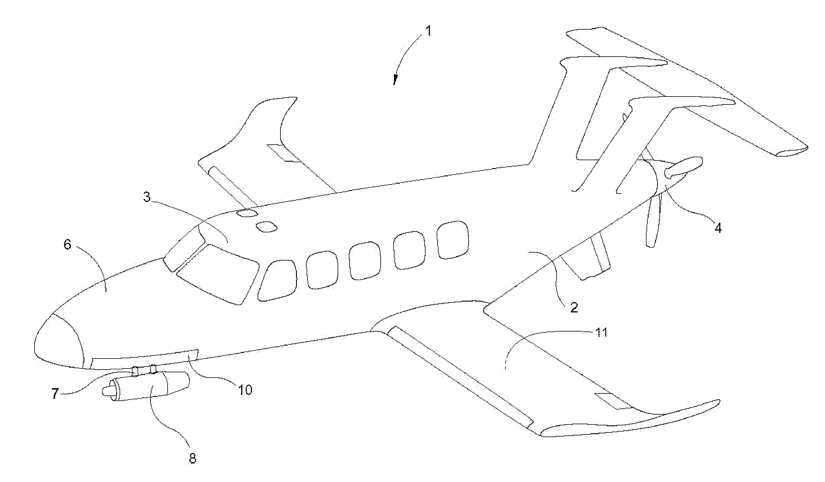
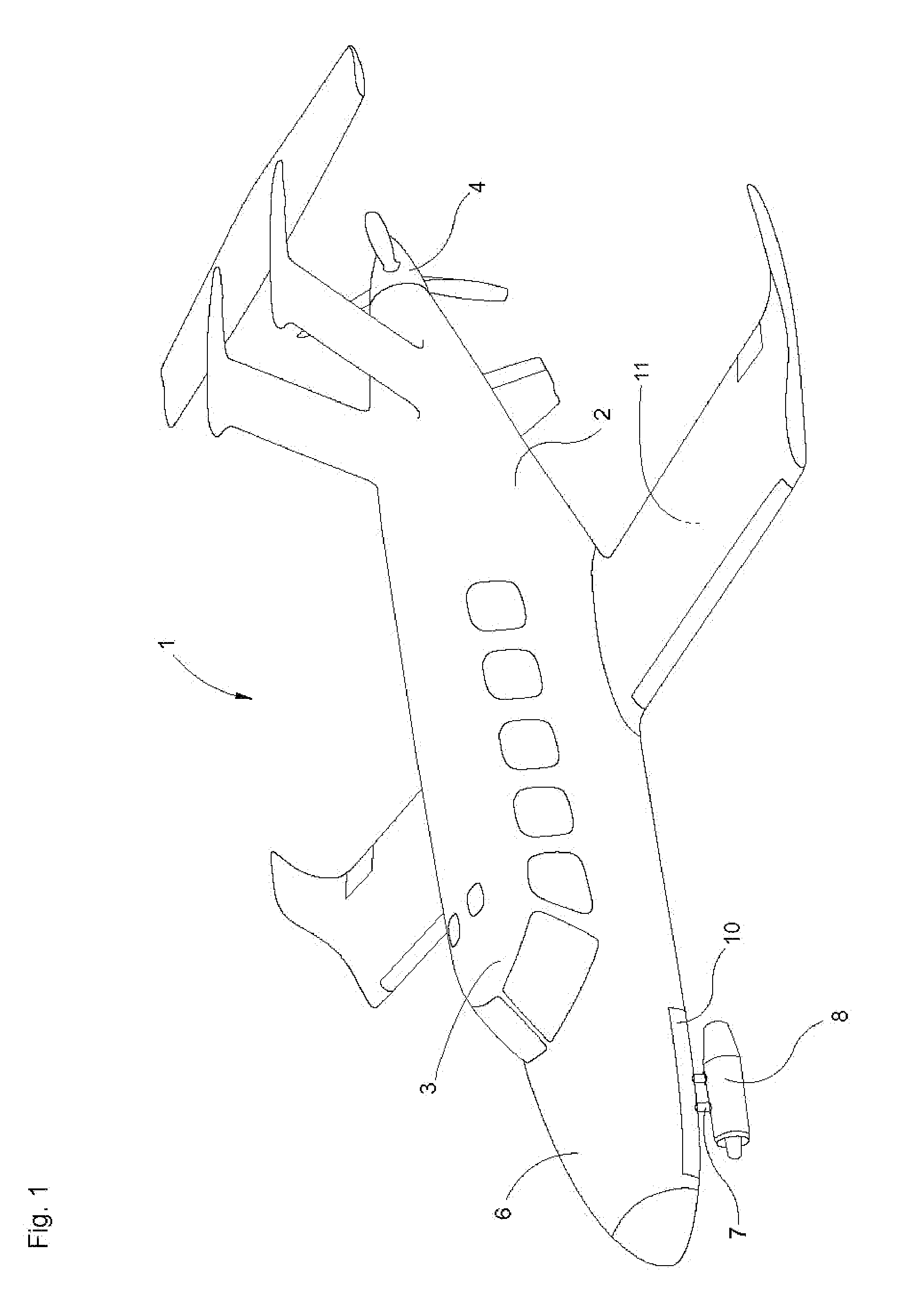
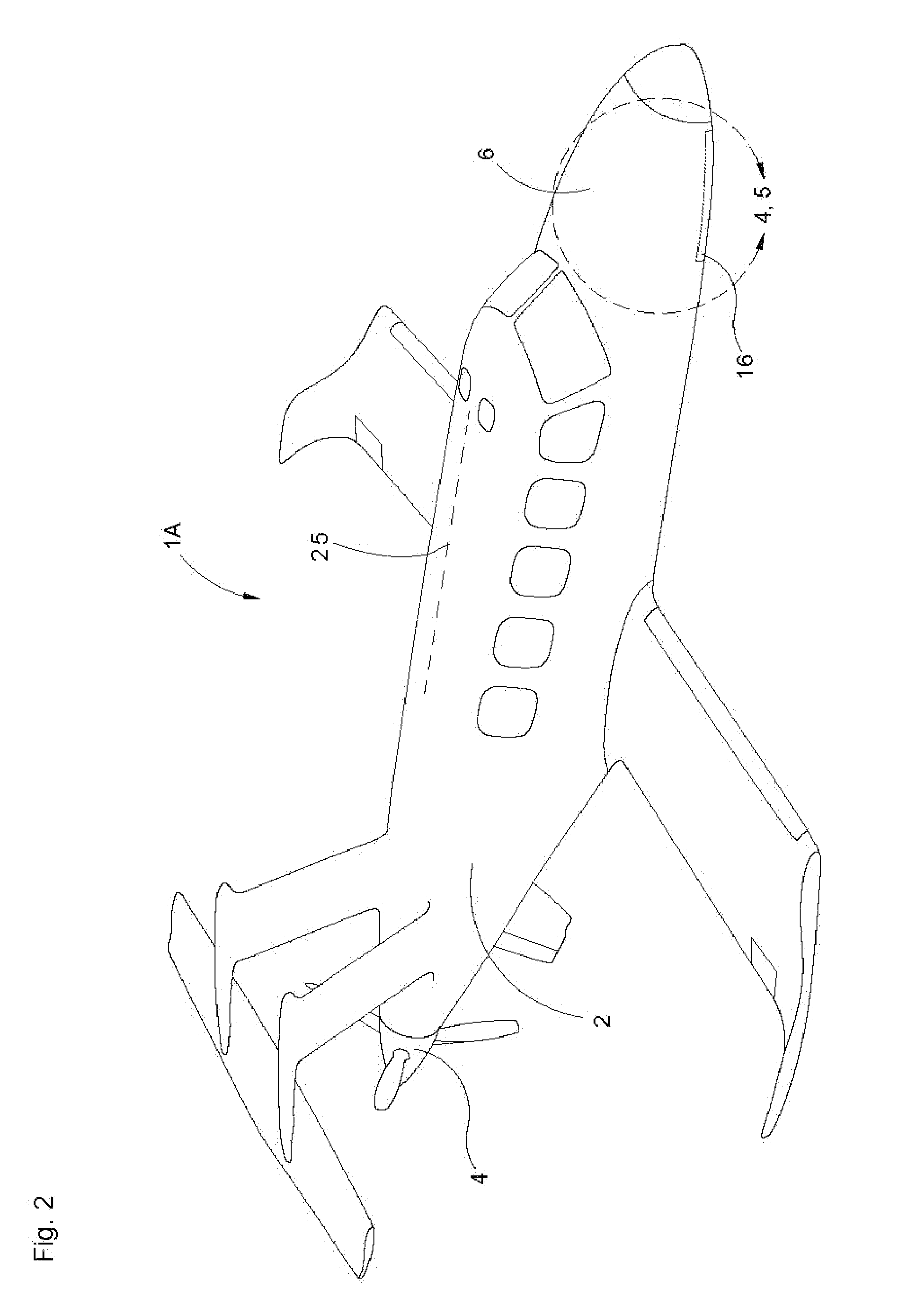
[0025]Referring now to the drawings, and in particular to FIG. 1, a preferred embodiment of the instant inventive fixed wing aircraft is referred to generally by Reference Arrow 1. The aircraft 1 represents an exemplary airplane having a conventional fuselage 2 housing a forward cockpit 3 for carriage of up to nine passengers or equivalent cargo, and being operated by a single pilot. A “pusher” configured variable pitch rear thrust propeller 4 is preferably mounted at the rearward or tail end of the fuselage 2 of the aircraft 1. In the depicted preferred embodiment, the “pusher” propeller 4 is powered by a rear fuselage mounted turbo-prop engine (not depicted within view).

[0026]Referring further to FIG. 1, the forward end of the fuselage 2 of the aircraft 1 preferably forms a substantially conical nose section 6. An auxiliary turbo-fan jet engine 8 is rigidly suspended upon at least a first support strut 11 which preferably extends laterally and downwardly from the nose section 6. T...


PUM


Abstract

A fixed wing aircraft having a fuselage having a forward end and a rearward end, the fuselage's forward end forming a nose section; the aircraft further having a primary thrust turbo-prop engine fixedly mounted upon the fuselage's rearward end; the aircraft further having an auxiliary thrust turbo-fan jet engine; the aircraft further having a pivot axle and support strut combination interconnecting the auxiliary thrust turbo-fan engine and the fuselage, the pivot axle and support strut combination positioning the auxiliary thrust turbo-fan jet engine within the fuselage's nose section; the aircraft further having an auxiliary thrust port extending through an outer wall of the nose section, the pivot axle and support strut combination being adapted for alternately moving the turbo-fan engine between first and second positions, the turbo-fan engine residing within the nose section upon movement to the first position, the turbo-fan engine outwardly overlying the auxiliary thrust port upon alternate movement to the second position.

Description

FIELD OF THE INVENTION[0001]This invention relates to internal combustion engine powered fixed wing aircraft. More particularly, this invention relates to engine mount configurations applicable to such aircraft.BACKGROUND OF THE INVENTION[0002]Propeller driven fixed wing aircraft typically have an optimal level flight cruising speed at which the airplane's air speed and the airplane's rate of fuel consumption are deemed to be acceptable in relation to each other. At speeds above an aircraft's optimal cruising speed, the benefits of reduced transit time are viewed as being negatively “outweighed” by the corresponding reduction in fuel economy. Conversely, at air speeds below the aircraft's optimal cruising speed, the resultant benefit of increased fuel economy is viewed as being negatively “outweighed” by the corresponding increase in transit time. Accordingly, an airplane's optimal cruising speed may vary from time to time as the result of changing demands of passengers on transit t...

Claims


Application Information

Patent Timeline
IPC IPC(8): B64C15/00
CPCB64D27/02B64D27/20B64D27/14
Inventor HUTTERER, JOSEPH A.
Owner HUTTERER GLADYS IRENE
Learn More