Lead member and boding method thereof and nonaqueous electrolyte electricity storing device

a technology of lead member and boding, which is applied in the direction of cell components, final product manufacturing, sustainable manufacturing/processing, etc., can solve the problems of corroding of metals with a higher ionization tendency, deteriorating electric properties but also mechanical strength at the bonded portion, and forming fragile alloy layers

Inactive Publication Date: 2008-05-01
SUMIDEN ASAHI IND LTD +1
View PDF6 Cites 33 Cited by
  • Summary
  • Abstract
  • Description
  • Claims
  • Application Information

AI Technical Summary

Benefits of technology

[0010]Therefore, it is an object of the invention to provide a lead member having a sufficient bonding strength mechanically and preventing a contact resistance at a bonded portion from being increased in a lead member bonded with a first member and a second member having different kinds of materials electrically and a method of bonding the lead member and a nonaqueous electrolyte electricity storing device.

Problems solved by technology

However, when the respective lead members are constituted by different metal materials, there poses a problem that a local battery is formed between the different kinds of metals at a bonded portion with an electrolysis solution constituted by water of condensation or the like, and the metal having a higher ionization tendency is corroded.
Further, when corrosion is brought about at the lead member, a contact resistance of the bonded portion is increased, and not only the electric property is deteriorated but also the mechanical strength at the bonded portion is deteriorated.
However, when laser welding for locally melting a metal by irradiating laser light is used, a fragile alloy layer is formed at a bonding boundary.
Therefore, there is a concern that a mechanical strength against tension or vibration at the bonded portion is low and the electric property is deteriorated.
Further, according to ultrasonic welding or the like, energy consumption is large, a facility thereof is large-scaled, operation thereof is complicated, and therefore, a fabrication performance is poor.

Method used


Image

  • Lead member and boding method thereof and nonaqueous electrolyte electricity storing device
  • Lead member and boding method thereof and nonaqueous electrolyte electricity storing device
  • Lead member and boding method thereof and nonaqueous electrolyte electricity storing device

Examples


embodiment 1

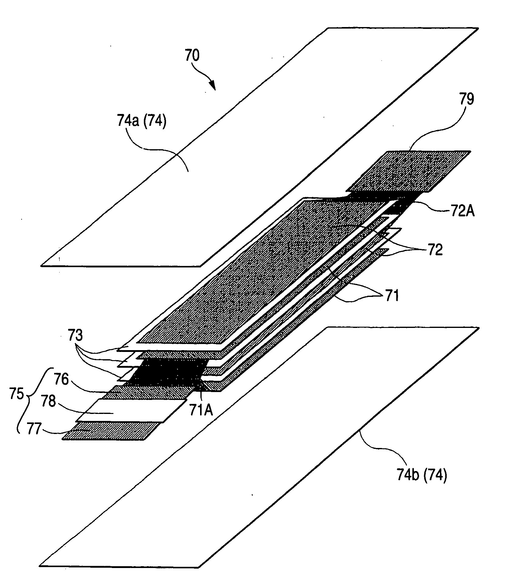
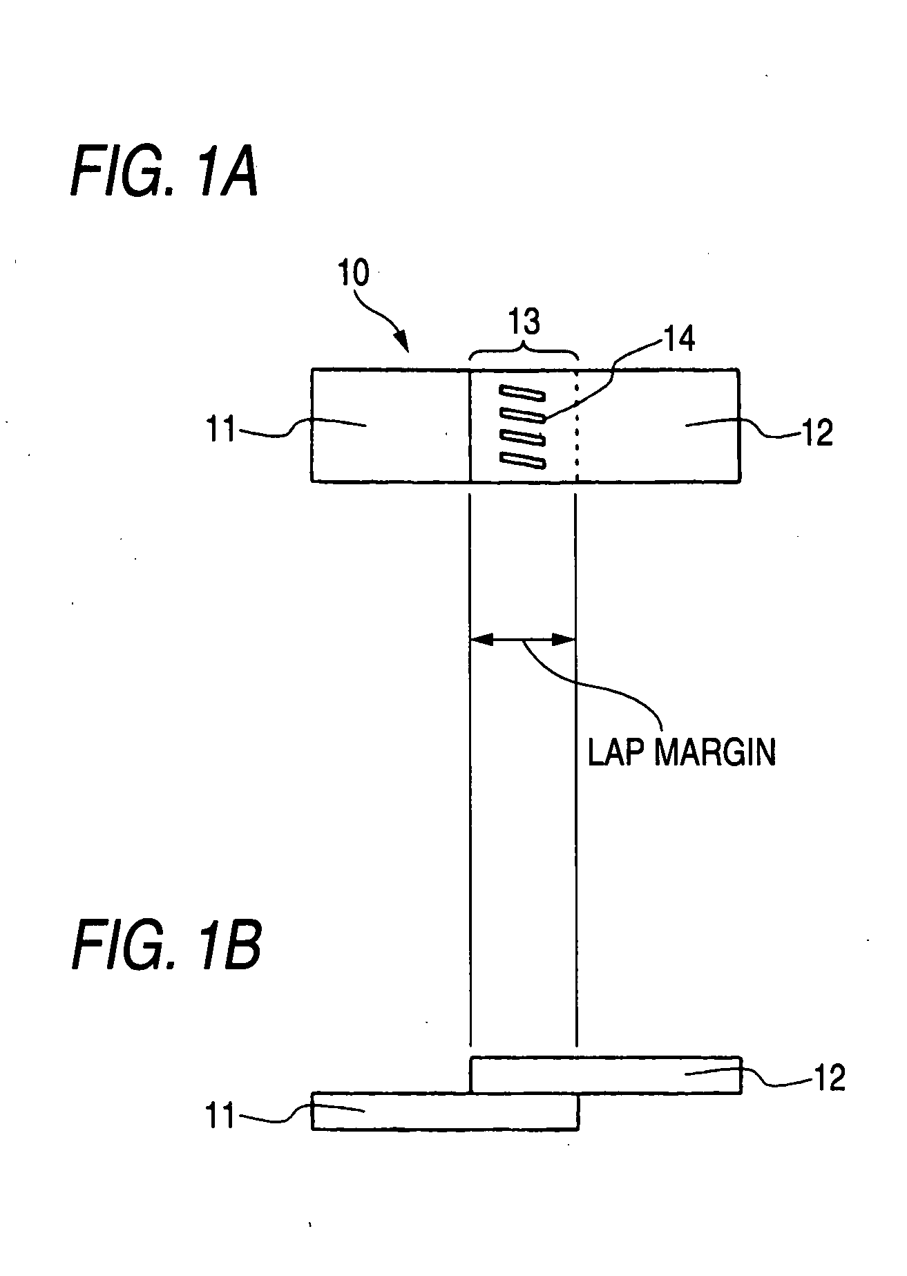
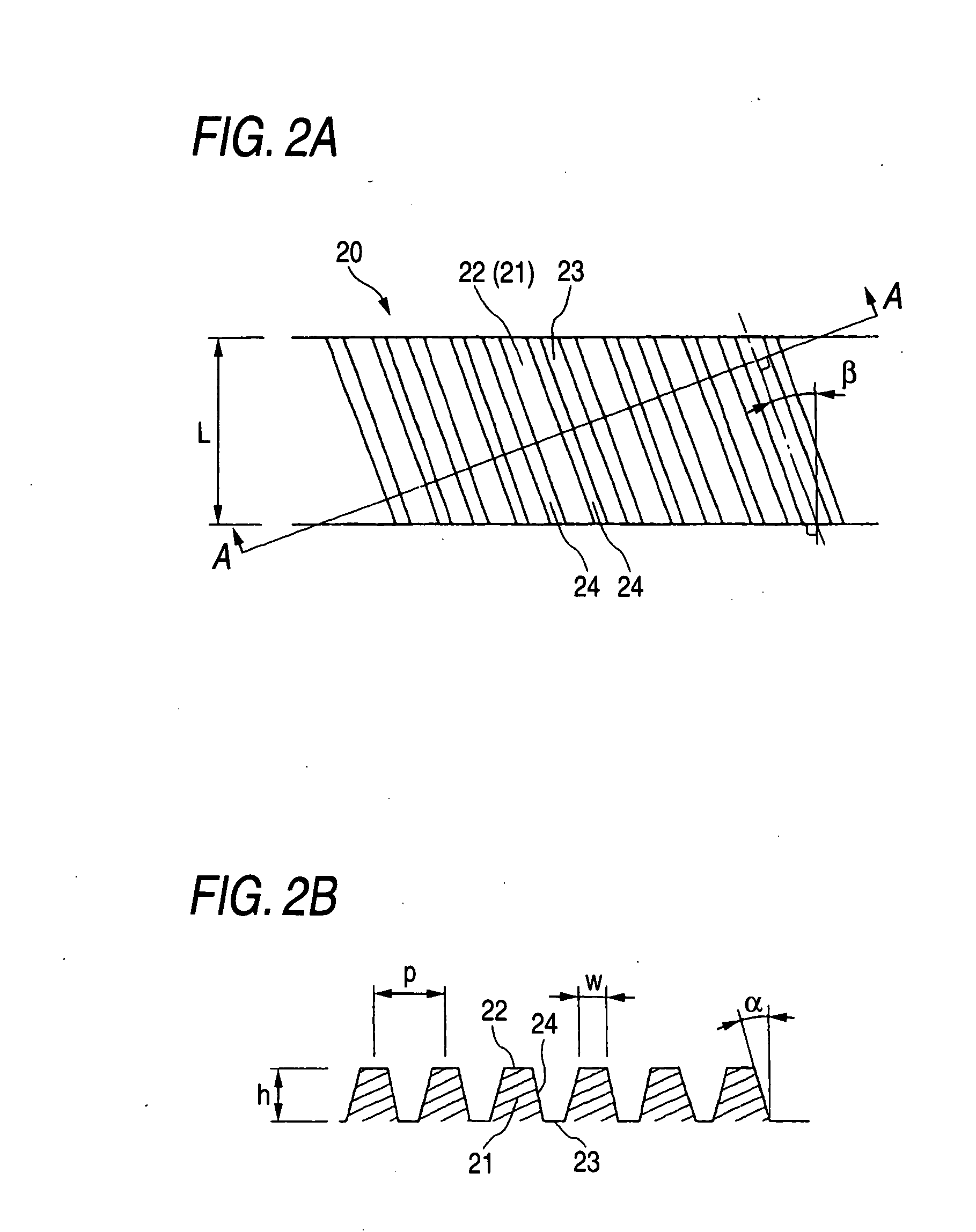
[0152]As a sample for pressure welding, an Al plate of 0.2 mm×50 mm×60 mm and a Ni plated Cu plate having the same size are prepared. The Al plate and the Ni plated Cu plate are partially overlapped, and an overlapped portion thereof is subjected to cold pressure welding. A dies consisted of a die having a projected portion and a plane die are used in pressure welding. In the dies, there are 3 kinds of modes for the die having the projected portion. A first one is a straight die. The die is a die for pressing the overlapped portion in a linear line shape in a width direction. A second die is a lengthwise teeth die. The die is constituted by a shape of aligning a plurality of the projected portions in an oval-like shape, and the respective projected portions are aligned such that a longitudinal direction thereof is in line with a longitudinal direction of the lead member. A third one is an inclined teeth die. The die is constituted by a shape of aligning a plurality of the projected ...

embodiment 2

[0180]Next, the shape of the inclined teeth die used in Embodiment 1 is changed and cold welding and flattening similar to those of Embodiment 1 are carried out by the die. The die used in the example is a ship-like shape die in which both ends of the projected portion are formed in a converging shape. The die is similar to the inclined teeth die in other specification except that the both end portions of the projected portion are formed in the converging shape.

[0181]When cold welding is carried out by using the ship-like shape die, a cold pressure welded mark is similar to that of the inclined teeth die in a mode of transcribing the shape of the projected portion of the die. However, after flattening is carried out, it can be recognized that the opening width of the cold pressure welded mark is reduced not only at the middle portion in the longitudinal direction of the cold pressure welded mark but also substantially over an entire length thereof. Therefore, it seems that in the ca...

embodiment 3

[0182]Next, the lead member of the invention by cold welding and a lead member for comparison by ultrasonic welding are fabricated and a tension resistant property and an electric property of the both are investigated.

[0183]Also in this case, a Ni plated Cu plate and an Al plate similar to those of Embodiment 1 are prepared and an overlapped portion thereof is subjected to cold welding or ultrasonic welding. A die used in cold welding is a die the same as the inclined teeth die in Embodiment 1. On the other hand, the ultrasonic welding is carried out by constituting bonding areas as 12 mm×3 mm×2 portions. Further, a sample subjected to cold welding is flatten by a pair of plane dies. Also the flattening condition is similar to that of the working condition of Embodiment 1.

[0184]The tension resistant property is measured by holding both ends of the provided lead member by a tensile tester and constituting a bonding strength by a tension at a time point of exfoliating the Ni plated Cu...


PUM

PropertyMeasurementUnit
thicknessaaaaaaaaaa
thicknessaaaaaaaaaa
thicknessaaaaaaaaaa

Abstract

A first member 11 and a second member 12 connected to each other are provided. The first member 11 is electrically connected to an electrode. The second member 12 is bonded to a position of the first member 11 remote from the electrode and is constituted by a material of a kind different from that of the first member 11. An overlapped portion 13 is formed at the first member 11 and the second member 12 and the overlapped portion 13 is bonded by cold welding. By the cold welding, the overlapped portion 13 is formed with a plurality of pressure marks 14 in a recess shape. Each cold pressure welded mark 14 is formed with a deformation mark reducing a depth of the cold pressure welded mark of the recess shape before plastic working by plastically working the overlapped portion 13 in a thickness direction thereof.

Description

BACKGROUND OF THE INVENTION[0001]The present invention relates to a lead member and a bonding method thereof and a nonaqueous electrolyte electricity storing device. Particularly, the invention relates to a lead member excellent in a mechanical strength and an electric property and a bonding method thereof and a nonaqueous electrolyte electricity storing device.[0002]In recent years, a reduction to practice of a nonaqueous electrolyte battery (for example, lithium ion battery or the like) has been progressed. A characteristic thereof resides in that in comparison with other battery, an energy output per unit volume or unit weight is high. Development of the nonaqueous electrolyte battery has been promoted as a power source of a mobile communication apparatus, a notebook personal computer, further, an electric vehicle or a hybrid vehicle. Particularly, small-sized formation, light-weighted formation of the battery as a power source has been requested, and attention is attracted to a ...

Claims


Application Information

Patent Timeline
Patent Type & Authority Applications(United States)
IPC IPC(8): H01M2/26H01G11/08H01G11/22H01G11/34H01G11/40H01G11/42H01G11/58H01G11/66H01G11/68H01G11/74H01G11/82H01G11/84H01M50/516H01M50/528H01M50/548H01M50/557H01M50/562H01M50/571
CPCH01M2/0212H01M2/202H01M10/0585H01M2/26H01M2/22Y02E60/10H01M50/557H01M50/528Y02P70/50H01M50/562H01M50/516H01M50/548
Inventor NII, HIROAKITANAKA, KOUSUKEHANAFUSA, KOJI
Owner SUMIDEN ASAHI IND LTD
Why Eureka
Try Eureka