Front electrode for use in photovoltaic device and method of making same

a photovoltaic device and front electrode technology, applied in the direction of basic electric elements, electrical apparatus, semiconductor devices, etc., can solve the problems of reducing the output power reducing the conductivity of the front electrode, and suffering of the photovoltaic device (e.g., solar cells) with such conventional tco front electrodes, etc., to reduce visible light reflection, increase the ir reflection capability, and reduce the effect of reflection

Inactive Publication Date: 2008-05-08
GUARDIAN GLASS LLC
View PDF99 Cites 111 Cited by
  • Summary
  • Abstract
  • Description
  • Claims
  • Application Information

AI Technical Summary

Benefits of technology

[0010]In certain example embodiments of this invention, the front electrode of a photovoltaic device is comprised of a multilayer coating including at least one transparent conductive oxide (TCO) layer (e.g., of or including a material such as tin oxide, zinc oxide, or the like) and at least one conductive substantially metallic IR reflecting layer (e.g., based on silver, gold, or the like). In certain example instances, the multilayer front electrode coating may include a plurality of TCO layers and/or a plurality of conductive substantially metallic IR reflecting layers arranged in an alternating manner in order to provide for reduced visible light reflections, increased conductivity, increased IR reflection capability, and so forth.
[0011]In certain example embodiments of this invention, the multilayer front electrode coating is designed to realize one or

Problems solved by technology

Unfortunately, photovoltaic devices (e.g., solar cells) with such conventional TCO front electrodes suffer from the following problems.
A lower sheet resistance may be achieved by increasing the thickness of such a TCO, but this will cause transmission of light through the TCO to drop thereby reducing output power of the photovoltaic device.
This IR radiation causes heat which increases the operating temperature of the photovoltaic device thereby decreasing the output power thereof.
Third, conventional TCO front electrodes such as pyrolytic tin oxide tend to reflect a significant amount of light in the regio

Method used


Image

  • Front electrode for use in photovoltaic device and method of making same
  • Front electrode for use in photovoltaic device and method of making same
  • Front electrode for use in photovoltaic device and method of making same

Examples


Embodiment Construction

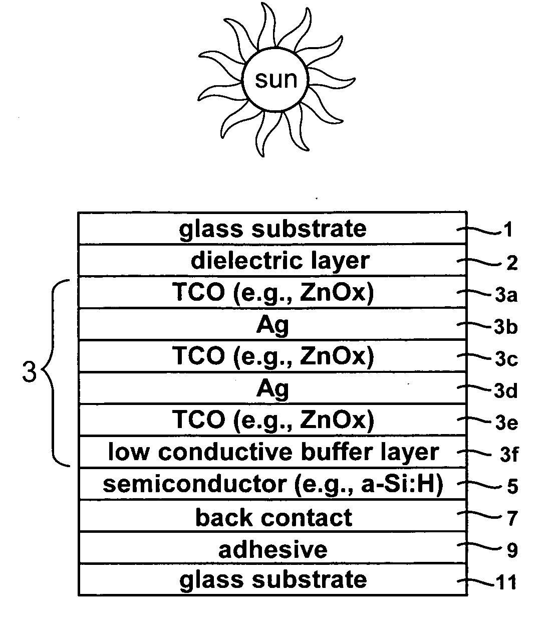
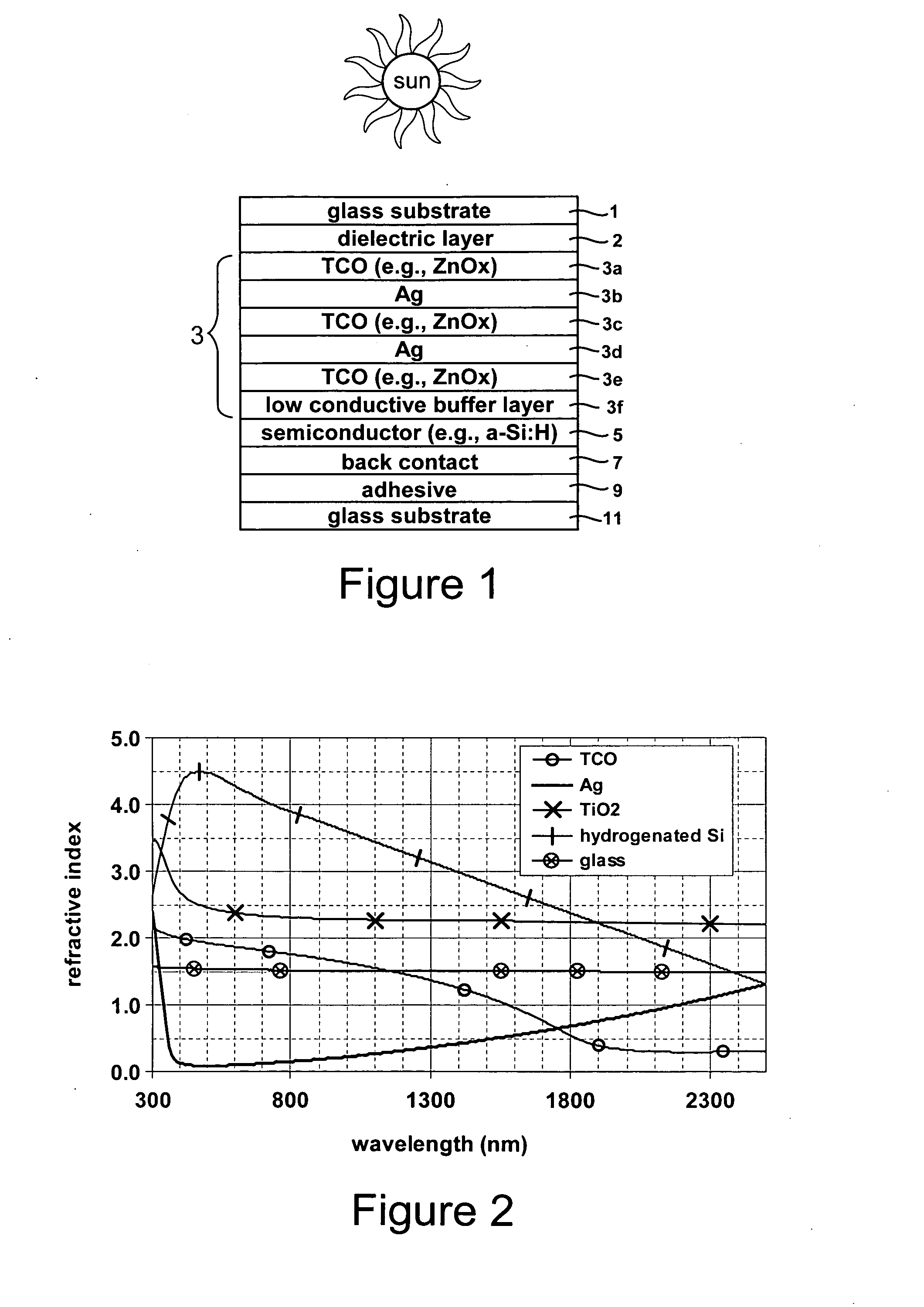
[0021]Referring now more particularly to the figures in which like reference numerals refer to like parts / layers in the several views.

[0022]Photovoltaic devices such as solar cells convert solar radiation into usable electrical energy. The energy conversion occurs typically as the result of the photovoltaic effect. Solar radiation (e.g., sunlight) impinging on a photovoltaic device and absorbed by an active region of semiconductor material (e.g., a semiconductor film including one or more semiconductor layers such as a-Si layers, the semiconductor sometimes being called an absorbing layer or film) generates electron-hole pairs in the active region. The electrons and holes may be separated by an electric field of a junction in the photovoltaic device. The separation of the electrons and holes by the junction results in the generation of an electric current and voltage. In certain example embodiments, the electrons flow toward the region of the semiconductor material having n-type con...


PUM


Abstract

This invention relates to a front electrode/contact for use in an electronic device such as a photovoltaic device. In certain example embodiments, the front electrode of a photovoltaic device or the like includes a multilayer coating including at least one transparent conductive oxide (TCO) layer (e.g., of or including a material such as tin oxide, zinc oxide, or the like) and at least one conductive substantially metallic IR reflecting layer (e.g., based on silver, gold, or the like). In certain example instances, the multilayer front electrode coating may include a plurality of TCO layers and/or a plurality of conductive substantially metallic IR reflecting layers arranged in an alternating manner in order to provide for reduced visible light reflection, increased conductivity, and/or increased infrared (IR) reflection capability.

Description

[0001]This invention relates to a photovoltaic device including an electrode such as a front electrode / contact. In certain example embodiments, the front electrode of the photovoltaic device includes a multi-layer coating having at least one transparent conductive oxide (TCO) layer (e.g., of or including a material such as tin oxide, zinc oxide, or the like) and at least one IR reflecting and conductive substantially metallic layer of or including silver, gold, or the like. In certain example embodiments, the multilayer front electrode coating is designed to realize one or more of the following advantageous features: (a) reduced sheet resistance and thus increased conductivity and improved overall photovoltaic module output power; (b) increased reflection of infrared (IR) radiation thereby reducing the operating temperature of the photovoltaic module so as to increase module output power; (c) reduced reflection and increased transmission of light in the region of from about 450-700 ...

Claims


Application Information

Patent Timeline
IPC IPC(8): H01L31/0224H01L31/04
CPCH01L31/022425H01L31/022466Y02E10/548H01L31/075H01L31/048H01L31/022483
Inventor LU, YIWEIDEN BOER, WILLEM
Owner GUARDIAN GLASS LLC
Why Eureka
Try Eureka