
Method Of Manufacturing An Auto-Calibrating Sensor

a technology of auto-calibrating and manufacturing methods, applied in the direction of instruments, catheters, diagnostic recording/measuring, etc., can solve the problems of serious healthcare complications, limb amputation and blindness, and enter a comatose state, so as to save time

Inactive Publication Date: 2008-05-15
LIFESCAN IP HLDG LLC
View PDF15 Cites 356 Cited by
  • Summary
  • Abstract
  • Description
  • Claims
  • Application Information

AI Technical Summary

Benefits of technology

[0048]When sensors are batch-manufactured, in either a flat-bed or staged process or in a continuous process, information representing the same calibration quantity may be transmitted to the wireless devices of a plurality of sensors at once or virtually simultaneously. In particular, a plurality of sensors may be placed into a protective enclosure and then information representing the same calibration quantity may be wirelessly transmitted to the wireless devices of those plurality of sensors at once or virtually simultaneously. This saves time and ensures the sensors are handled to the minimum degree possible.

Problems solved by technology

Failure to control blood glucose levels within a recommended range can result in serious healthcare complications such as limb amputation and blindness.
Furthermore, failure to accurately measure blood glucose levels may result in hypoglycaemia.
Under such conditions the diabetic patient may initially enter a comatose state, and if untreated may die.
People suffering from diabetes are often at a higher risk of other diseases.
Diabetes also contributes to kidney disease, which occurs when the kidneys do not filter properly and protein leaks into urine in excessive amounts, which eventually can cause kidney failure.
Diabetes is a cause of damage to the retina at the back of the eye and also increases risk of cataracts and glaucoma.
Nerve damage caused by diabetes may interfere with the ability to sense pain and contributes to serious infections.
This can be undesirable since it can take time for a user to learn proper use of the process involved in diabetes testing and errors of operation by a user can occur.
It is also undesirable since a user may be put off by tedious repetitive action of inserting calibration codes into a blood glucose monitoring system, which reduces the accuracy of glucose levels and can lead to complicated health conditions.
It is further undesirable since repetitive testing on a localised area results in lack of feeling especially around the finger tips (nerve damage) and calluses can form making operation of the buttons difficult.
This creates a problem for diabetics as technology pushes miniaturisation to new limits, partially driven by the need to make blood glucose meter systems acceptable and not ‘out of place’ i.e. to make the diabetic patient to feel as ‘normal’ as possible.
Users can also have difficulty in using such devices because of the resultant effects of their medical conditions again causing difficulty, entering data via buttons or keypads etc.
Another problem with the insertion of calibration codes is again that long term diabetes sufferers who have not managed to fully control their illness may be suffering from cataracts or glaucoma.
Such illnesses make the use and operation of blood glucose meter systems problematic with partially sighted sufferers, for whom basic testing could be considered an achievement, let alone inputting of calibration codes into a blood glucose meter.
Another problem with the insertion of calibration codes is that blood glucose testing is a time consuming affair.
Performing time consuming manual steps potentially minimises the frequency a diabetic tests himself and can lead to a downward spiral for the user e.g., lack of testing resulting in further complications which in turn discourages a diabetic from testing further, for example because of the need to lance and enter calibration strip data into a blood glucose meter.
The confirmation of test calibration data on a display such as an LCD display and / or LED display can also lead to problems for users of all ages and users of all levels of diabetes.
During pre-breakfast testing a diabetic may have difficulty focusing on such a small display and could enter an incorrect calibration code.
Similarly, a conscientious diabetic wishing to test himself at the post evening meal or pre-bed time may be tired and feeling drowsy and may inadvertently input the incorrect calibration code into the blood glucose meter.
Again, this could lead to complicated health conditions especially where a diabetic is about to sleep for the night thinking his glucose level is normal when in actual fact he may be entering an unconscious state because he is in a hypoglyeaemic condition.
Also, if a diabetic does enter into a hypoglycaemic condition and is found by his partner or care giver, then it would further cause confusion if the care giver is not trained in glucose testing.
The care giver may not however, be aware that a manual cumbersome calibration code needs to be inputted into the blood glucose meter before testing, resulting in an incorrect calibration code being inputted leading to further complications.
Similarly, since test strips are small in size, visually-impaired diabetics have difficulty in knowing how many test strips are left in a vial.
This can be a problem to diabetics especially when they leave their normal surroundings for a length of time e.g. travelling away on a whim, on holiday etc. and could potentially leave them without enough test strips for the duration of their time away from home.
Not only is this potentially dangerous to a diabetic, but also is inconvenient.
Another challenge facing the diabetes monitoring industry is the use of monitoring devices by people with disabilities.
When we use the expression “tolerances and variations” we are, of course speaking of small effects, indeed effects so small that it may be uneconomical to engineer them out of the manufacturing process; hence the need for calibration in the first place.
These small effects are large enough to upset the accuracy of blood glucose measurements and indeed the accuracy of any analyte measurement where a certain level of accuracy is needed.
But now we are speaking of a process that is very difficult if not impossible to engineer down to the same level of tolerances.
In any case, the altered or new calibration quantities will no longer be properly represented by the calibration information that was previously printed on the label, which in turn means that the sensor must be recalibrated.

Method used


Image

  • Method Of Manufacturing An Auto-Calibrating Sensor
  • Method Of Manufacturing An Auto-Calibrating Sensor
  • Method Of Manufacturing An Auto-Calibrating Sensor

Examples


Embodiment Construction

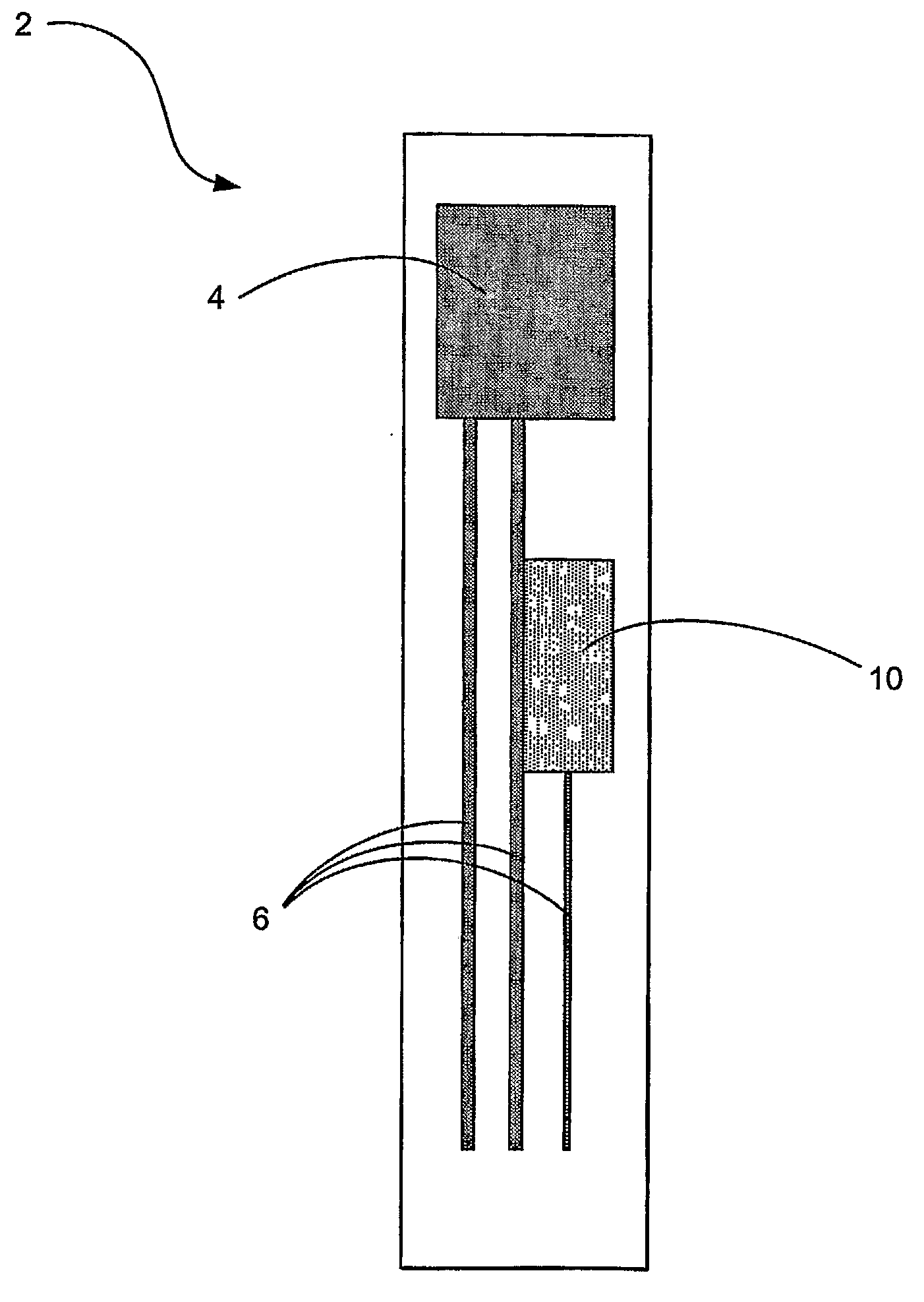
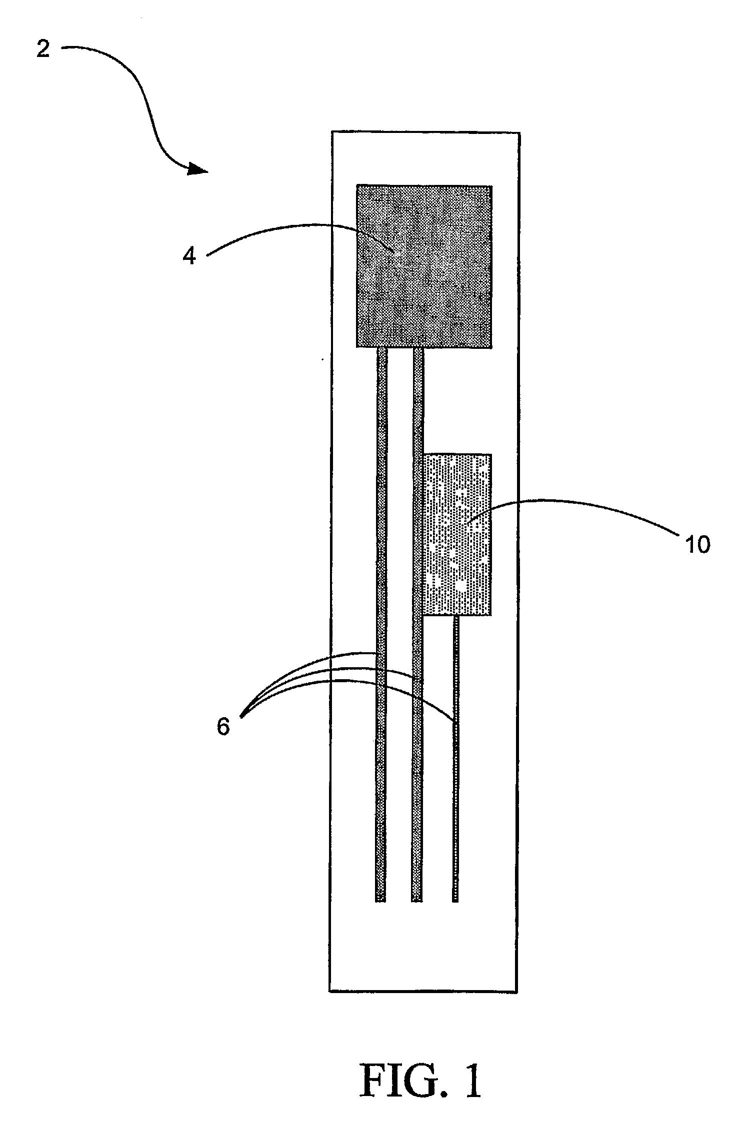
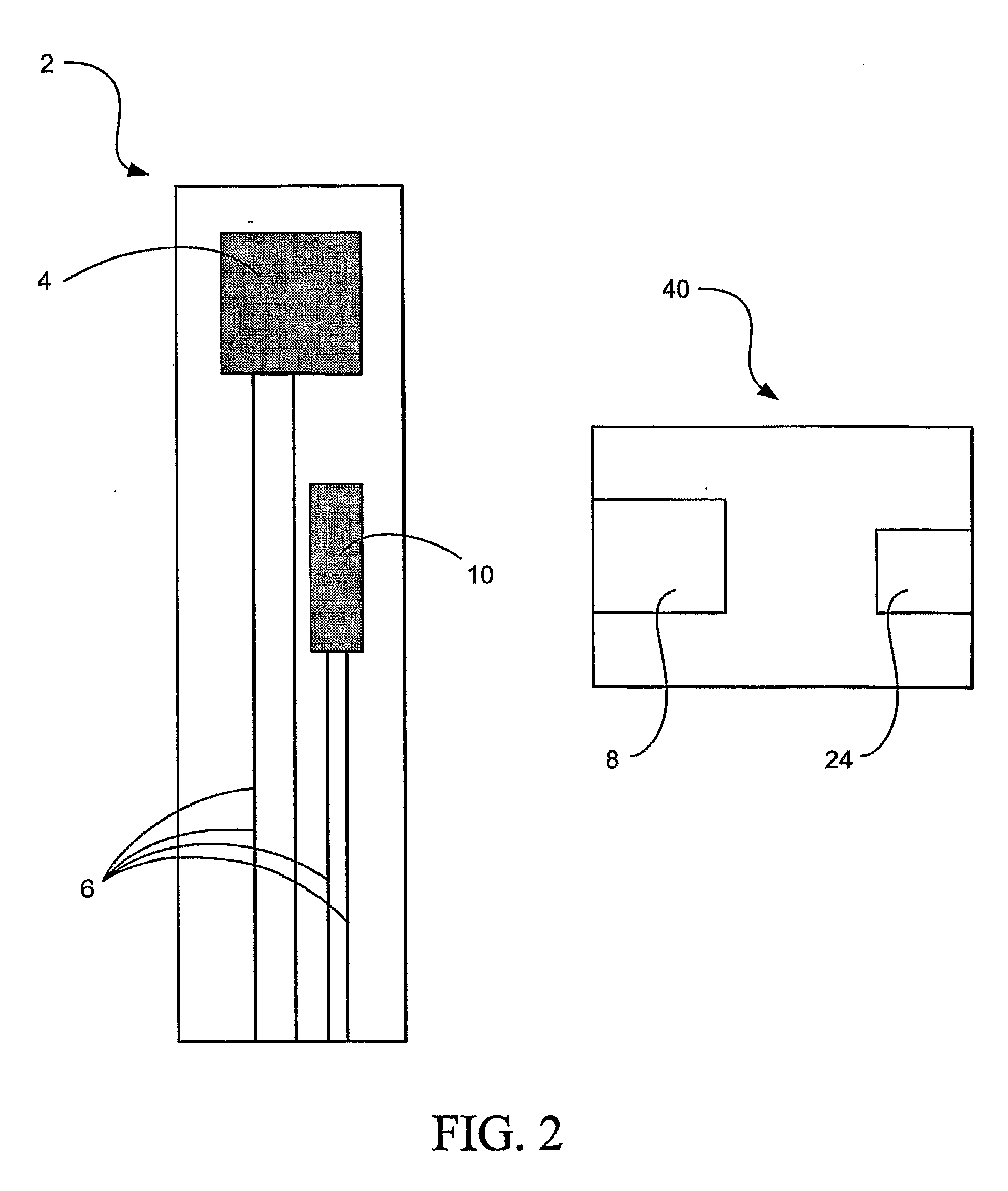
[0072]FIG. 1 shows a test element strip or test strip 2 having a sample area 4, electrical tracks 6, and a Radio Frequency Identification (RFID) tag 10. RFID (Radio Frequency Identification) is a technique which is able to carry data in suitable transponders, generally known as tags, and to retrieve data, by machine-readable means, at a suitable time and place to satisfy particular application needs.

[0073]An example RFID system may have, in addition to at least one tag, a transceiver or means of reading or interrogating the tags and optionally means of communicating the data received from a tag to an information management system. Transceivers are also known as interrogators, readers, or polling devices. Typically the system may also have a facility for entering or programming data into the tags. RFID tags contain an antenna and an integrated circuit. Various configurations of RFID tags are currently available in the marketplace and one such supplier is Texas Instruments® and the RI...


PUM

PropertyMeasurementUnit
frequencyaaaaaaaaaa
frequencyaaaaaaaaaa
frequencyaaaaaaaaaa

Abstract

The invention concerns a sensor that, when exposed to a fluid, develops a measurable characteristic that is a function of the level of an analyte in the fluid and of a calibration quantity of the sensor. A calibration quantity is some physical, chemical or other inherent property that the sensor possesses that affects its response to the analyte. The sensor includes an RFID tag that receives, stores and conveys information representing the calibration quantity. The wireless device is incorporated into or attached to the sensor during the manufacturing process and before the sensor is calibrated. The wireless device can be written wirelessly once the calibration has been done. This does not involve any additional handling of the sensor and can be done once the sensor has been placed into a protective enclosure. Because of this, the process of wirelessly transmitting the calibration information to the wireless device does not alter any pre-existing calibration quantities and neither does it introduce any new calibration quantities, thus preserving the calibration of the sensor even though the sensor has been wirelessly modified to carry information representing its calibration quantity.

Description

PRIORITY [0001]This application claims priority benefits under 35 U.S.C. §§ 120 and 371 of International Application PCT / US2005 / 031286 filed on 31 Aug. 2005, which claims priority benefits to U.S. Provisional Application Ser. No. 60 / 606,334 filed on 31 Aug. 2004, which both applications are hereby incorporated by reference in their entireties into this application.FIELD OF THE INVENTION [0002]The invention relates to an auto-calibrating sensor for use, in healthcare management, law-enforcement, dope-testing, sanitation or otherwise, for measuring the concentration of any analyte, such as glucose, lactate, urate, alcohol, therapeutic drugs, recreational drugs, performance-enhancing drugs, biomarkers indicative of diseased conditions, hormones, antibodies, metabolites of any of the aforesaid, combinations of any of the aforesaid, other similar indicators or any other analyte in a fluid, especially a physiological fluid such as blood, interstitial fluid (ISF) or urine. Much of the foll...

Claims


Application Information

Patent Timeline
Patent Type & Authority Applications(United States)
IPC IPC(8): A61B5/145B05D5/12G08B1/08G01N33/66G01N27/00
CPCA61B5/1411A61B5/14514A61B5/14532A61B5/14865A61B2562/085A61B5/0022A61M5/1723G06F19/3406G06F19/3418G06F19/3456A61K47/48992A61B5/150022A61B5/150068A61B5/150083A61B5/150175A61B5/150358A61B5/150412A61B5/150503A61B5/150526A61B5/150793A61B5/15087A61B5/151A61B5/15186A61B5/155A61B5/157A61K47/6957G16H40/40G16H40/63
Inventor MCCLUSKEY, JOSEPHGRIFFITH, ALUNROBINSON, GRENVILLESPALDING, GORDONTAYLOR, DAVIDBECK, ERICA MARY
Owner LIFESCAN IP HLDG LLC
Learn More