Method of Supplying Lubrication Oil in Cold Rolling

a technology of cold rolling and lubrication oil, which is applied in the direction of manufacturing tools, machines/engines, mechanical equipment, etc., can solve the problems of inability to achieve a suitable range of friction coefficient between mild steel and hi-tension steel sheets within the operating range, and achieve the effect of improving the specific consumption of lubrication oil and high productivity

Active Publication Date: 2008-05-22
NIPPON STEEL CORP +1
View PDF8 Cites 15 Cited by
  • Summary
  • Abstract
  • Description
  • Claims
  • Application Information

AI Technical Summary

Benefits of technology

[0019]According to the method of supplying lubrication oil of the present invention, regardless of the rolled product, rolling from the low speed region to the high speed region by one type of lubrication oil can be realized, rolling trouble can be avoided and high productivity realized, and the specific consumption of lubrication oil can be improved.

Problems solved by technology

Hi-tension steel sheet is hard and is susceptible to seizure, so at the time of high speed rolling, it is necessary to control the friction coefficient to a smaller one not giving rise to seizure.
If overly reducing the friction coefficient at the time of high speed rolling, there is a danger of slip occurring due to excessive lubrication.
The inventors developed rolling lubrication oil considering rolling of hi-tension steel sheet as shown in FIG. 3, but were not able to realize a suitable range of the friction coefficient for both mild steel and hi-tension steel sheet within the operating range up to now.

Method used


Image

  • Method of Supplying Lubrication Oil in Cold Rolling
  • Method of Supplying Lubrication Oil in Cold Rolling
  • Method of Supplying Lubrication Oil in Cold Rolling

Examples


example 1

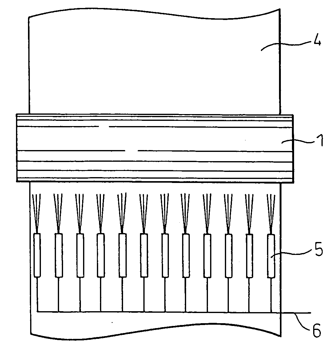
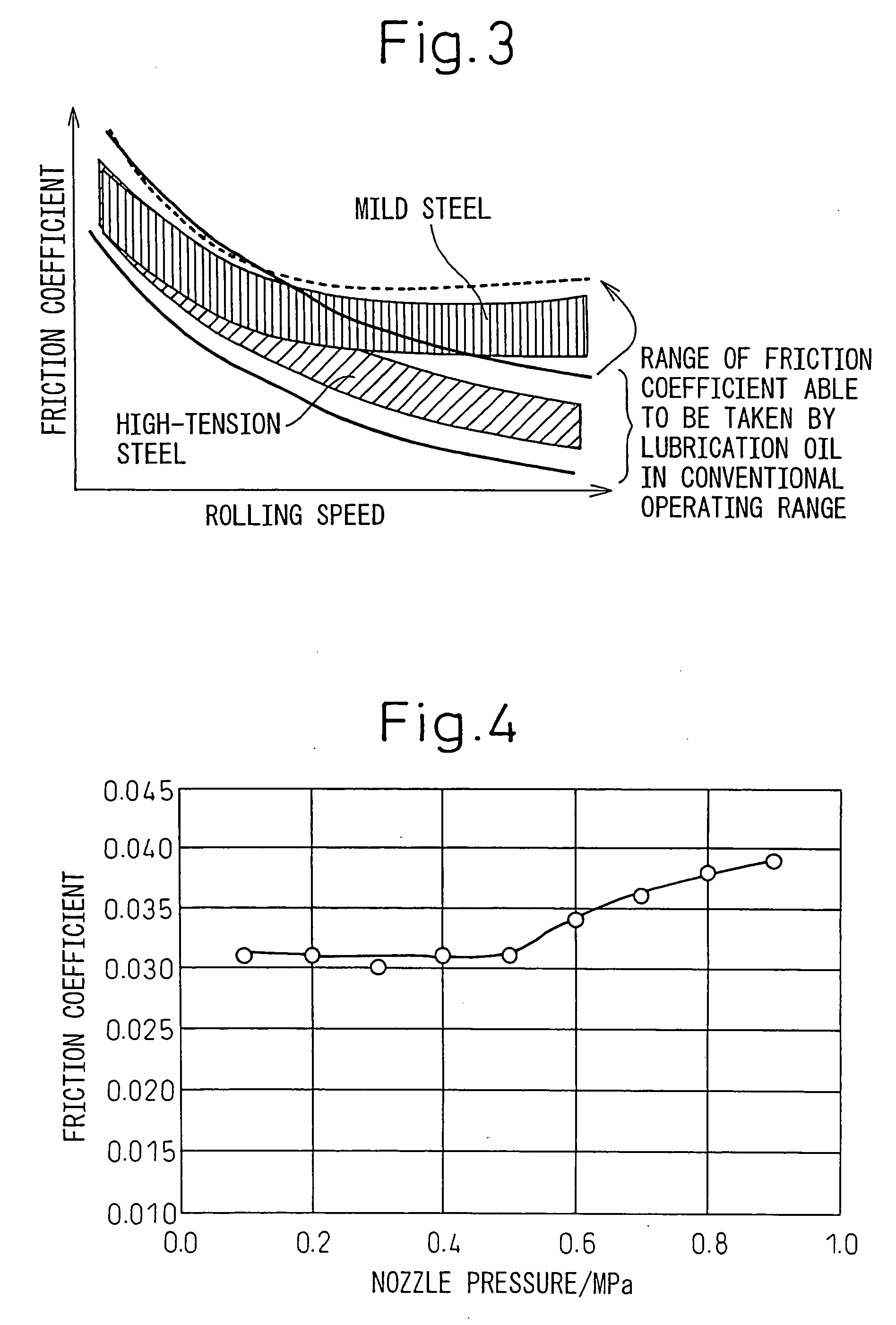
[0036]To confirm the effects of the present invention, the inventors changed the lubrication nozzle pressure and conducted experiments on rolling coils. For the experiment, the laboratory rolling machine shown in FIG. 6 was used. Reference numerals la and lb indicate work rolls, 2a and 2b intermediate rolls, and 3a and 3b backup rolls. Reference numeral 4 indicates a rolled material of a sheet width of 300 mm made of mild steel set to a rolling reduction ratio of 11% (sheet thickness reduced from 0.25 mm to 0.2 mm). Reference numeral 5 indicates a lubrication oil supply nozzle, the diameter of the work rolls is 300 mm, the diameter of the intermediate rolls is 360 mm, and the diameter of the backup rolls is 600 mm. The lubrication oil used is a 13% emulsion heated in a tank to 60° C. and based on refined palm oil. The rolling speed was increased from 500 m / min and the operation ended at a maximum rolling speed of 1800 m / min. At a rolling speed of 1200 m / min or less, the lubrication ...

example 2

[0038]To hold the total supply rate constant when changing the lubrication nozzle pressure, the inventors conducted rolling experiments by different lubrication supply methods such as (i) the method of supplying lubrication oil based on reducing the number of nozzles used (see FIG. 5), (ii) the method of supplying lubrication oil based on changing the size of the lubrication oil discharge port of the nozzles when changing the lubrication nozzle pressure, and (iii) the method of supplying lubrication oil using lubrication nozzles comprised of pairs of low pressure nozzles and high pressure nozzles. The other conditions were made to match with the conditions of Example 1. In the method of supplying lubrication oil of (i), the inventors investigated the relationship between the lubrication nozzle pressure and supply rate in advance. When increasing the lubrication nozzle pressure, as shown in FIG. 5, they stopped the supply from the nozzles evenly at the left and right in the sheet wid...

example 3

[0040]In Examples 1 and 2, examples of control based on the upper side of the rolled material were explained. Here, the inventors controlled the supply of the lubrication oil separately at the upper side and back side of the rolled material by the method of controlling the size of the lubrication oil discharge port of the nozzles for maintaining the lubrication oil supply rate constant under the conditions of Example 2 (ii), that is, changing the lubrication nozzle pressure.

[0041]At the back side, of the rolled material, the lubrication oil sprayed from the nozzles drops down due to gravity, so lubrication easily becomes insufficient compared with the upper side of the rolled material and slip does not easily occur, so the inventors investigated the range by which the lubrication nozzle pressure can be reduced and the amount of reduction of the specific consumption of lubrication oil by (xi) the method of supplying lubrication oil of reducing the lubrication nozzle pressure at the b...


PUM

PropertyMeasurementUnit
pressureaaaaaaaaaa
pressureaaaaaaaaaa
thicknessaaaaaaaaaa

Abstract

The present invention provides a method of supplying lubrication oil in cold rolling for stable rolling without heat scratches or slip and realizing high productivity and improvement of the specific consumption of lubrication oil, that is, a method of supplying lubrication oil in cold rolling for lubricating rolling in cold tandem rolling of metal sheet by supplying a predetermined kind of emulsion lubrication oil comprised of a mixture of rolling oil and water at the rolling stand inlet side from nozzles, the method of supplying lubrication oil in cold rolling characterized by measuring or estimating the pressure in the lubrication nozzle pipe (lubrication nozzle pressure), controlling the lubrication nozzle pressure of any rolling stand where lubrication is liable to become excessive with the predetermined emulsion lubrication oil to 0.5 MPa or more, and, while doing so, supplying the lubrication oil to the roll bite inlet of the stand by direct injection.

Description

TECHNICAL FIELD[0001]The present invention relates to a method of supplying emulsion lubrication oil enabling high productivity and improvement of the specific consumption of oil in a rolling machine for a metal material, in particular cold tandem rolling machines having a group of four or more stands of cold rolling machines.BACKGROUND ART[0002]In cold tandem rolling by emulsion lubrication, it is known that the emulsion lubrication oil supplied to the rolled material at the stand inlet side or the rolls separates into water and oil, the effect of the wedge shape formed at the roll bite inlet causes the oil to mainly be drawn into the roll bite due to its higher viscosity than the water, and therefore an oil film is formed between the rolls and the rolled material. Note that below, the phenomenon of the lubrication oil supplied to the rolls and the rolled material separating into water and oil and spreading is called “plate-out”.[0003]In general, the effect of the wedge shape drawi...

Claims


Application Information

Patent Timeline
Patent Type & Authority Applications(United States)
IPC IPC(8): F01M1/00
CPCB21B1/36B21B45/0251B21B45/0233B21B27/10B21B45/02B21B1/22B21B1/28
Inventor TAKAHAMA, YOSHIKISHIRAISHI, TOSHIYUKIOGAWA, SHIGERUVANEL, LUCHAURET, GUYLAUGIER, MAXIMEMASSON, PASCAL
Owner NIPPON STEEL CORP
Why Eureka
Try Eureka