Harmonics measurement instrument with in-situ calibration

a measurement instrument and in-situ calibration technology, applied in the direction of instruments, multi-tester circuits, speed/acceleration/shock measurement, etc., can solve the problem of exactly the wrong conclusion about the apparent reversal of the direction of harmonic power flow, and the distortion of voltage and current, etc. problem, to achieve the effect of reducing the cost of a highly stable and accurate instrumen

Inactive Publication Date: 2008-05-22
MCEACHERN ALEXANDER +1
View PDF26 Cites 32 Cited by
  • Summary
  • Abstract
  • Description
  • Claims
  • Application Information

AI Technical Summary

Problems solved by technology

However, in real grids, the voltages and currents are distorted, and contain both a fundamental frequency component and numerous smaller harmonic components.
The inductive nature of typical power distribution systems means that this phase angle is often close to 90 degrees, so even a small error in measuring this parameter can lead to an apparent reversal of the direction of harmonic power flow, because the direction of flow reverses when the angle reaches 90 degrees.
For this reason, an error of just one degree can lead to exactly the wrong conclusion about the direction of harmonic power flow.
A significant source of phase angle measurement error, as well as ratio error, comes from the split-core, clamp-on current transducers commonly used to measure in-situ current waveforms.
However, as known to those familiar with the art, this type of sensor introduces phase angle and ratio errors.
However, other current transducer errors are a function of quantities that vary with time and location, such as temperature, humidity, the amount of corrosion on the mating surfaces of the magnetic core, the amount of mechanical wear on the hinge of the jaws, the smoothness of the mating surfaces of the magnetic core, and the spring pressure holding the jaws closed.
These transducer errors cannot be calibrated at a factory or laboratory, because they vary with time and location.
Additional errors are introduced in the harmonic measurements by the chain of electronics between the current transducer and the measurement results: amplifiers, filters, analog-to-digital converters, and the like.
However, some errors in this chain of electronics vary with temperature, humidity, time, ambient magnetic field, and other local parameters which may be known or unknown.
These errors cannot be calibrated at a factory or laboratory.
As is familiar to one familiar with the state of the art, similar errors arise in the chain of electronics needed for voltage harmonic measurements.
Selecting and purchasing components that are stable with respect to age, temperature, and humidity is difficult and expensive.
For example, Burns et al. in U.S. Pat. No. 6,377,037 disclose a meter with a power factor compensation technique that inserts a delay into the sampled current or voltage stream; however, Burns et al. do not disclose in-situ calibration for field measurements, and therefore cannot compensate for variations in sensors and amplifiers that would have developed since the instrument's most recent laboratory calibration.
Also, Gandhi in U.S. Pat. No. 6,911,813 discloses an electronic meter that delays the digital voltage and / or current signal to compensate for phase shift error; but Gandhi does not disclose in-situ calibration for field measurements, and therefore cannot compensate for variations in sensors and amplifiers that would have developed since the meter's most recent laboratory calibration.
Although this disclosure recognizes the problem of measuring the phase angle between voltage and current accurately, Voisine et al. do not disclose in-situ calibration for field measurements, and therefore cannot compensate for variations in sensors and amplifiers that would have developed since the power meter's most recent laboratory calibration.
However, Whitehead et al. do not disclose in-situ calibration using non-sinusoidal test input signals, i.e., those that contain harmonic content.
However, Longini does not disclose a calibration unit that is built into the meter itself and that performs calibration at the site where the power meter will be installed.
Furthermore, Longini does not disclose a method to perform phase angle calibration.
In summary, none of these methods disclose in-situ calibration, at harmonic frequencies, of both the amplitude response of the current and voltage measurement circuits, including their associated current transducers and voltage probes, and the phase angle response between them, at the measurement sites immediately before making measurements.

Method used


Image

  • Harmonics measurement instrument with in-situ calibration
  • Harmonics measurement instrument with in-situ calibration
  • Harmonics measurement instrument with in-situ calibration

Examples


Embodiment Construction

—DESCRIPTION

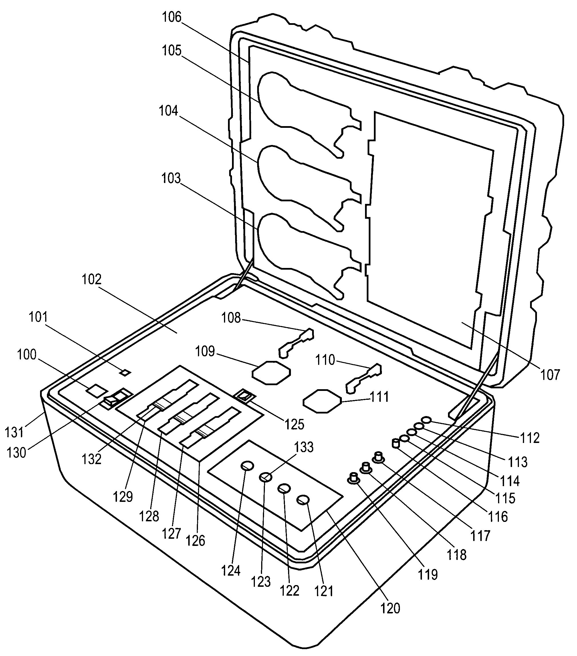
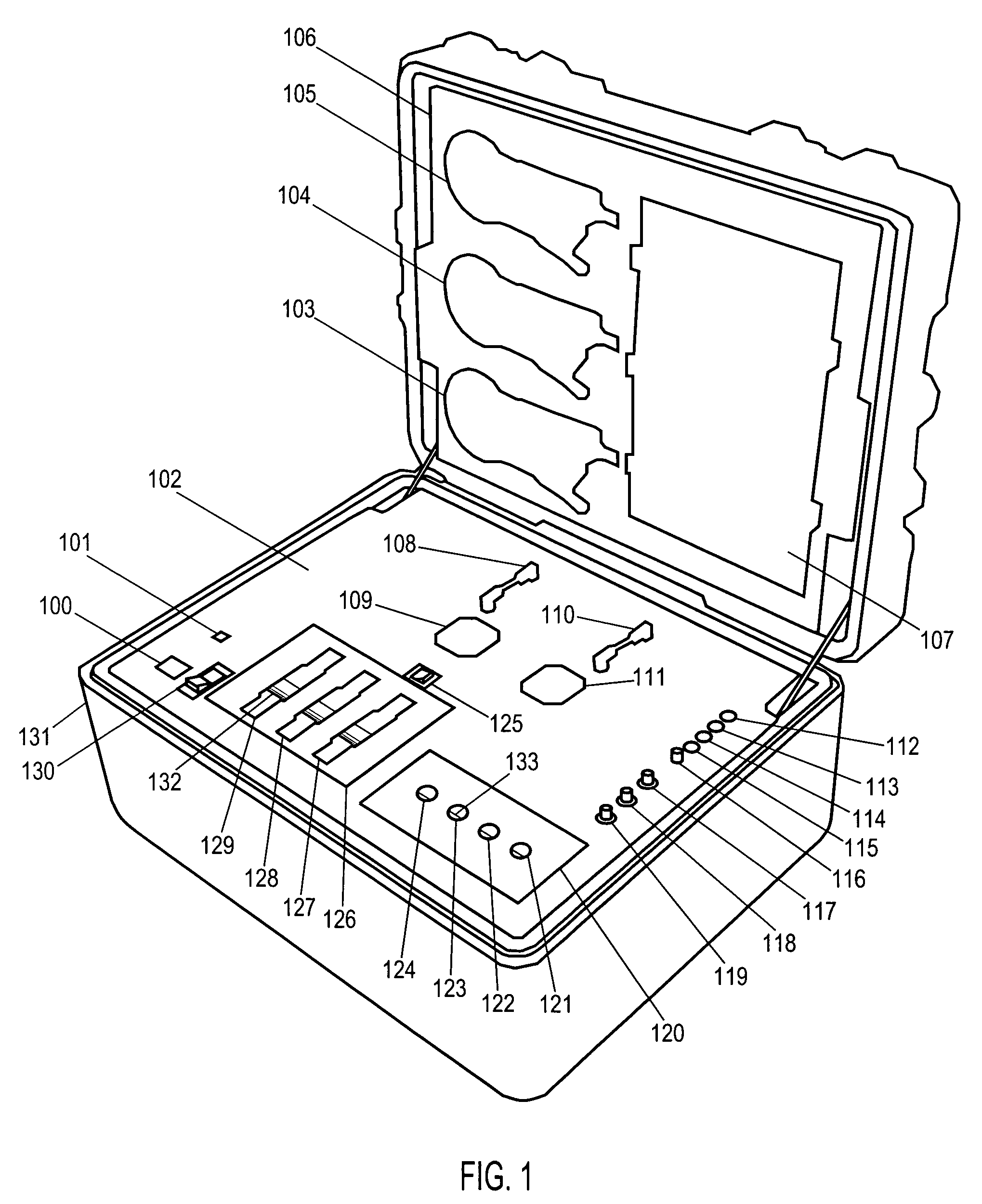
[0037]Turning first to FIG. 1, we see a representative embodiment of the present invention. The instrument consists of an instrument panel 102 and a storage lid 106 above. The storage lid 106 contains spaces 103,104,105,107 to store the current transducers, voltage probes, and other components when not in use.

[0038]A key element of the present invention is the built-in current calibration unit 126, which contains a tube 132 through which the current loops 12, seen in FIG. 3, are wound. This tube 132 is preferably constructed a material that is magnetically transparent and electrically insulating, such as polycarbonate resin thermoplastic manufactured by the General Electric Company of Fairfield, Conn., under the trademark Lexan. The outside diameter of this tube is preferably selected to mechanically match the inside diameter of the current transducers 20,21,22 shown in FIG. 3. During in-situ calibration, the current transducers 20,21,22 are inserted through slots 127,12...


PUM


Abstract

A portable harmonics measurement instrument performs in-situ self-calibration of its current transducers and their associated measurement channels and of its voltage probes and their associated measurement channels. In-situ self-calibration is performed immediately before making a measurement on the alternating current power distribution grid. In-situ self-calibration is performed by means of a built-in voltage reference source and a built-in current reference source, which generate highly-accurate voltage and current calibration waveforms with harmonic components.

Description

CROSS REFERENCES TO RELATED APPLICATIONS[0001]None.BACKGROUND[0002]1. Field of Invention[0003]This invention relates to electronic measurement equipment, more specifically to portable equipment for making in-situ harmonic voltage measurements and harmonic current measurements on alternating current (AC) power conductors. The equipment performs an in-situ calibration of its measurement channels, including their associated current transducers, immediately before making an in-situ measurement.[0004]2. Background of the Invention[0005]Voltages and currents on electric power distribution grids generally operate at 50 Hertz or 60 Hertz. This frequency is called the fundamental frequency. In an ideal grid, the voltages and currents will be perfectly sinusoidal with respect to time. However, in real grids, the voltages and currents are distorted, and contain both a fundamental frequency component and numerous smaller harmonic components. The harmonic components are typically caused by nonli...

Claims


Application Information

Patent Timeline
Patent Type & Authority Applications(United States)
IPC IPC(8): G01R35/04G01R19/00
CPCG01R19/2513G01R15/125G01R35/005
Inventor MCEACHERN, ALEXANDERMUH, MATTHEW
Owner MCEACHERN ALEXANDER
Why Eureka
Try Eureka