Spike converter

a power converter and converter technology, applied in the direction of power conversion systems, dc-dc conversion, instruments, etc., can solve the problems of increasing the size and cost of the components, and the converter is low power, so as to reduce the size and cost of the reactive components, reduce the size and cost, and the converter is highly efficient

Inactive Publication Date: 2008-05-22
MHZ POWER SOURCES
View PDF16 Cites 3 Cited by
  • Summary
  • Abstract
  • Description
  • Claims
  • Application Information

AI Technical Summary

Benefits of technology

[0005]The present invention exploits the advantages of spike mode operation which is essentially a very low duty cycle mode of operation of a fly-back converter with automatic pulse skipping mode resulting in significant size and cost reduction of the reactive components such as the power transformer the output capacitance as well as the de-rating of the switching element. The present invention provides a highly efficient power converter for low power applications. Its low duty cycle allows the converter to function at a lower frequency while retaining the benefit of high frequency operation in the

Problems solved by technology

Customarily, the starting point of a prior art converter design is to set the duty cycle around 50% for low line full load co

Method used


Image

  • Spike converter
  • Spike converter
  • Spike converter

Examples


Embodiment Construction

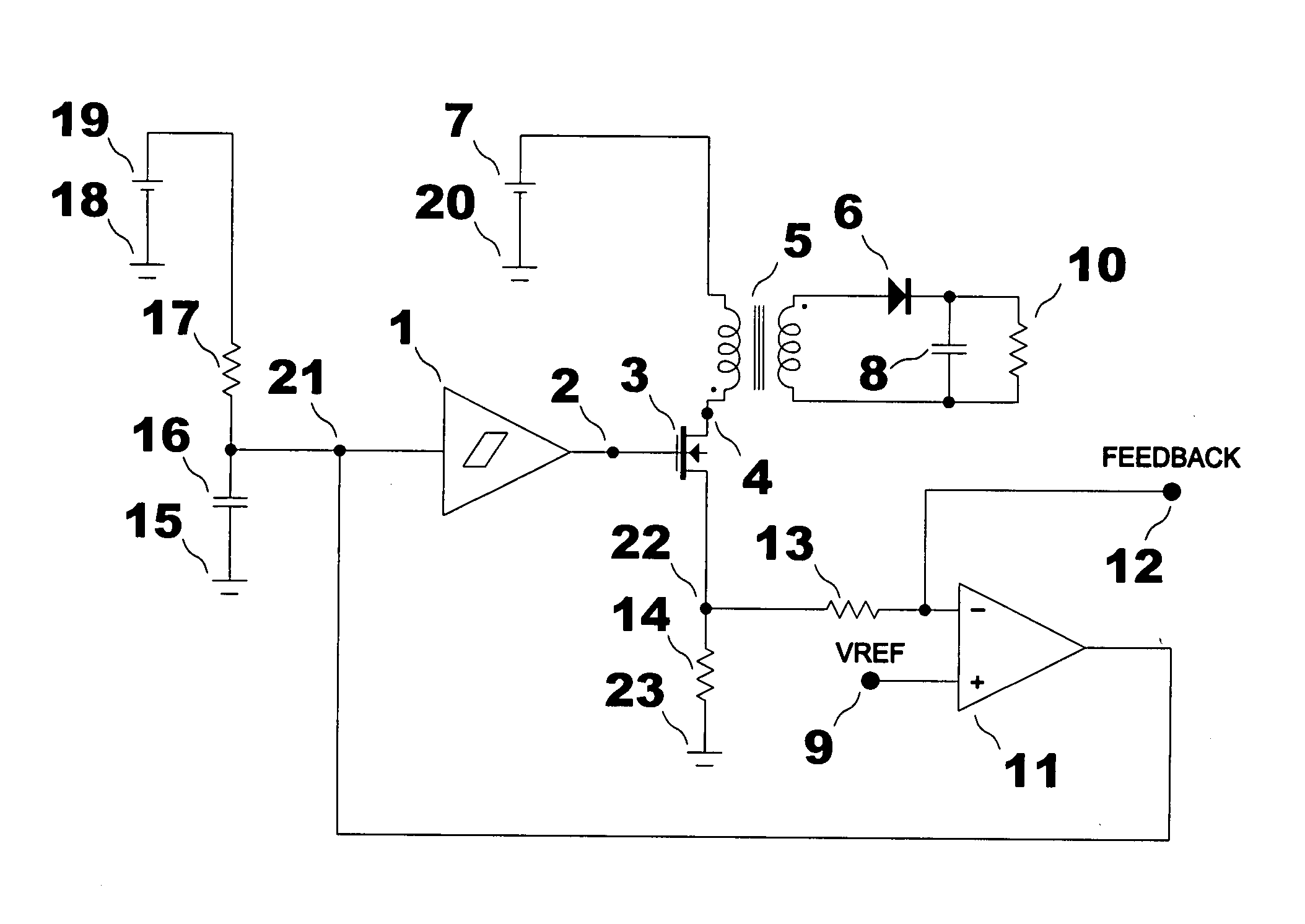
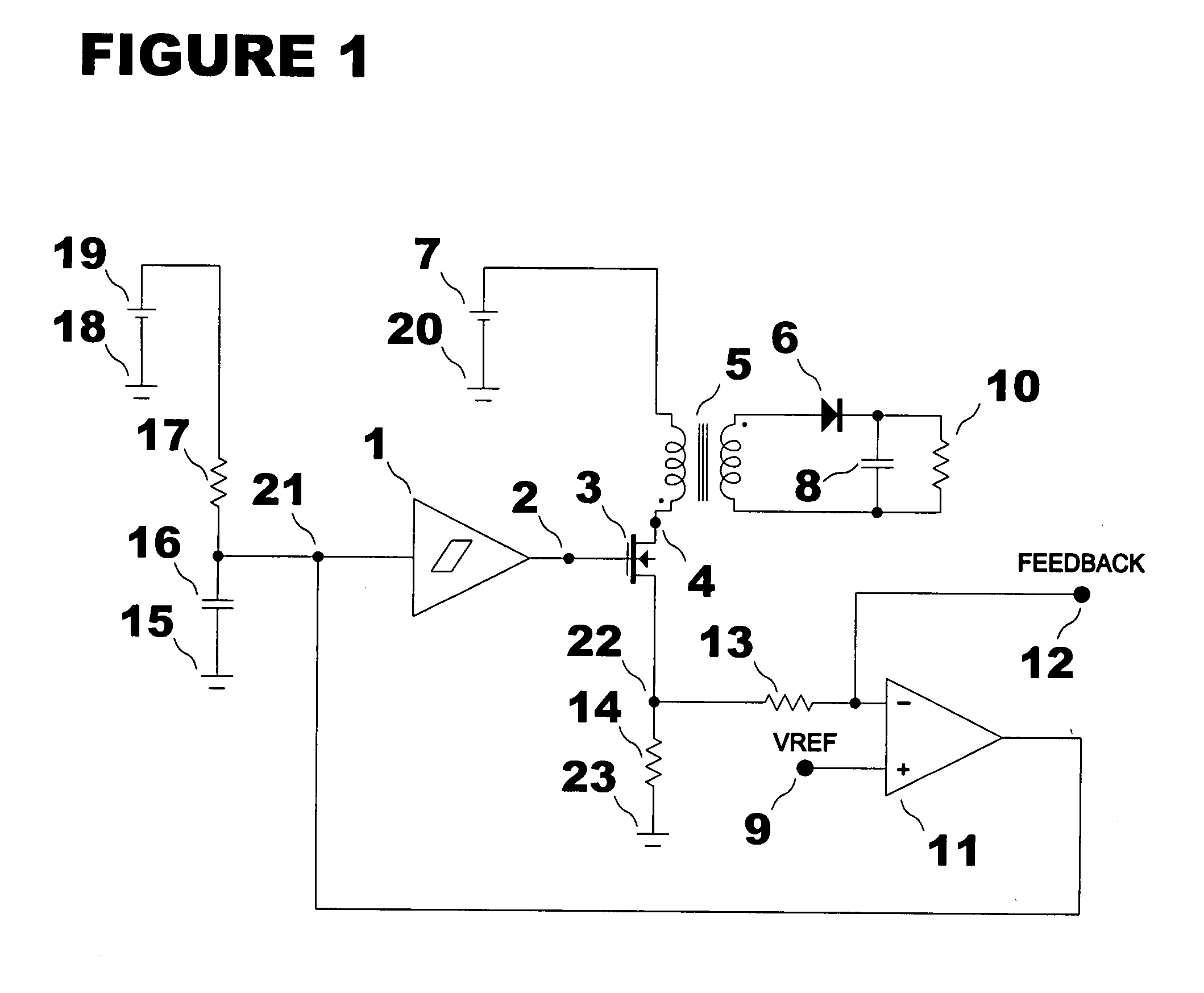
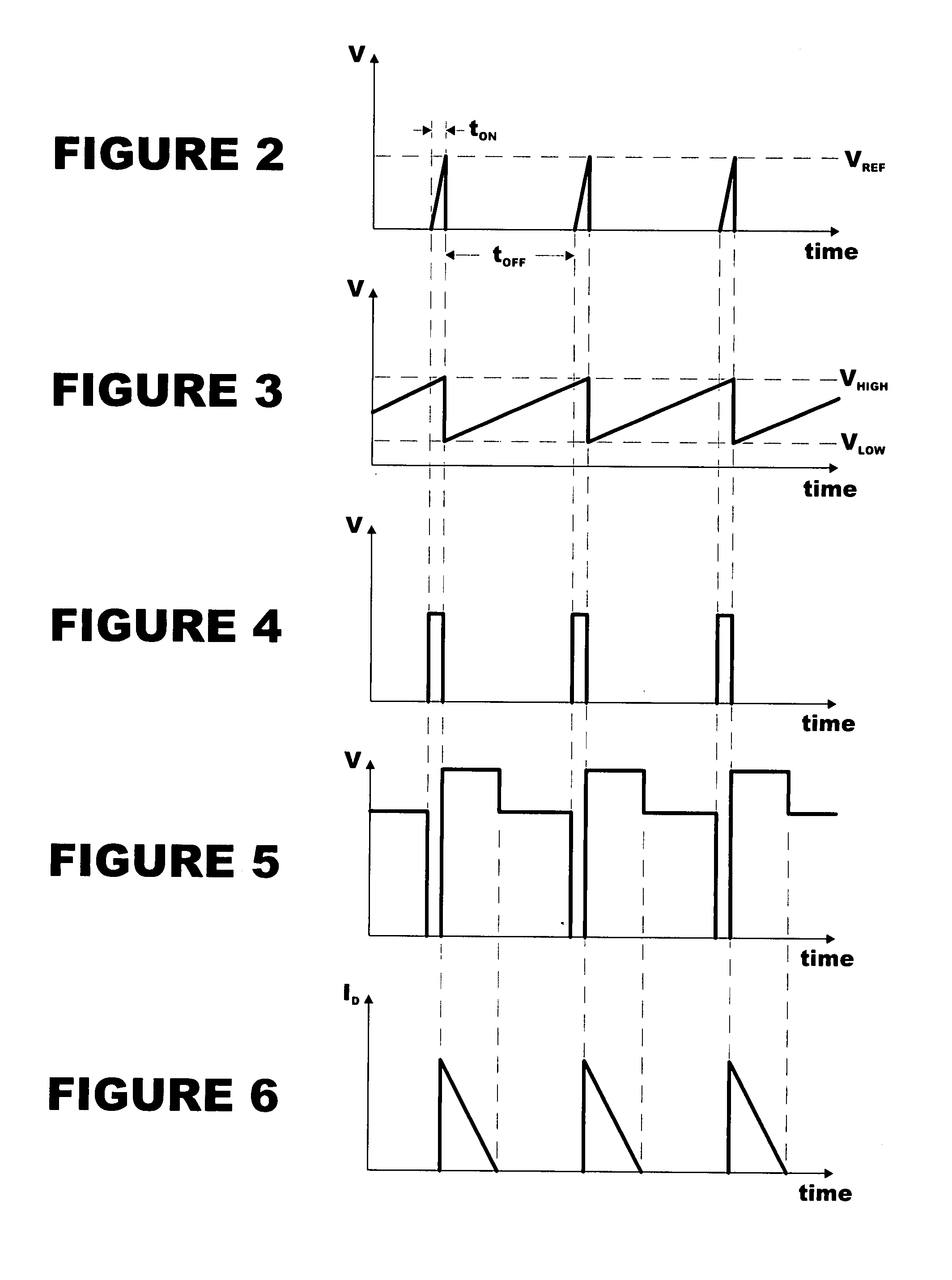
[0012]In order to better understand the embodiment of the present invention, a spike converter will be described with reference to FIG. 1 and corresponding waveforms in FIGS. 2 through 6. One terminal of a timing capacitor 16 is connected to a timing resistor 17 as in FIG. 1. The junction of said timing capacitor 16 and timing resistor 17 is further connected to the input of a comparator with hysteresis 1 and the output of a current sense comparator 11. A waveform as in FIG. 3 is developed at junction point 21. The other terminal of said timing resistor 17 is connected to the positive terminal of a bias supply 19 and the other terminal of said timing capacitor 16 is connected to the common ground 15. Ground points 15, 18, 20 and 23 represent a common point and are only separated for the purposes of this illustration. The negative terminal of bias supply 19 is connected to common ground 18.

[0013]The output of the comparator with hysteresis 1 is connected to the input terminal of a sw...


PUM


Abstract

The present invention is a spike converter providing a special mode of operation of a low power fly-back converter in a very narrow duty cycle range in particular. This spike operation minimizes the size of the required reactive components such as that of the power transformer and output capacitance. The present invention automatically achieves low idle power consumption due to the nature of the feedback under fixed, narrow duty cycle or spike operation. The spike operation is defined by the lower limit of the on time of the switching element being generated by the sum of the propagation delays of a current sense comparator and an off time pulse generating comparator.

Description

BACKGROUND OF THE INVENTION[0001]1. Field of the Invention[0002]The present invention generally relates to power converters. Specifically, the present invention relates to power converters for applications where power requirements are on the order of a few watts. More specifically, the present invention relates to those power converters having a universal input voltage range and needing to meet the requirements of “green” power, very low power consumption, under light load conditions.[0003]2. Description of the Prior Art[0004]Prior art embodiments customarily use a light or no load detection system by sensing one of the parameters related to loading and then initiating burst mode operation to reduce standby power and to increase light load efficiency. One such embodiment is a method whereby a comparator is used to monitor a feedback voltage relative to a reference level which, if exceeded, causes a burst mode block to be activated in order to keep idle power consumption low. Customa...

Claims


Application Information

Patent Timeline
IPC IPC(8): H02M3/335
CPCH02M3/33507
Inventor MESZLENYI, IVAN
Owner MHZ POWER SOURCES
Why Eureka
Try Eureka