Vibratingly Stirring Apparatus, and Device and Method for Processing Using the Stirring Apparatus

a technology of stirring apparatus and stirring chamber, which is applied in the direction of sealing device, electrolysis component, transportation and packaging, etc., can solve the problems of inapplicability of method and limited electric current density to only about 5 to 6 a/dm, and achieve high-quality products and improve production efficiency

Inactive Publication Date: 2008-05-22
JAPAN TECH CO LTD (JP)
View PDF14 Cites 28 Cited by
  • Summary
  • Abstract
  • Description
  • Claims
  • Application Information

AI Technical Summary

Benefits of technology

[0010]In view of these problems, it is an object of the present invention is to expand the applicable range of the vibration stirring apparatus by adding functions different from its basic function, and to further improve performance unique to that applicable range.

Problems solved by technology

Even with this method however, the electrical current density is limited to only about 5 to 6 A / dm2.
Also, irregularities occur in the product film thickness so this method is not practical to use.

Method used


Image

  • Vibratingly Stirring Apparatus, and Device and Method for Processing Using the Stirring Apparatus
  • Vibratingly Stirring Apparatus, and Device and Method for Processing Using the Stirring Apparatus
  • Vibratingly Stirring Apparatus, and Device and Method for Processing Using the Stirring Apparatus

Examples


first embodiment

Milk Sterilizer

[0212]Milk was sterilized using the liquid treatment apparatus described for FIG. 34. The processing conditions were as follows.

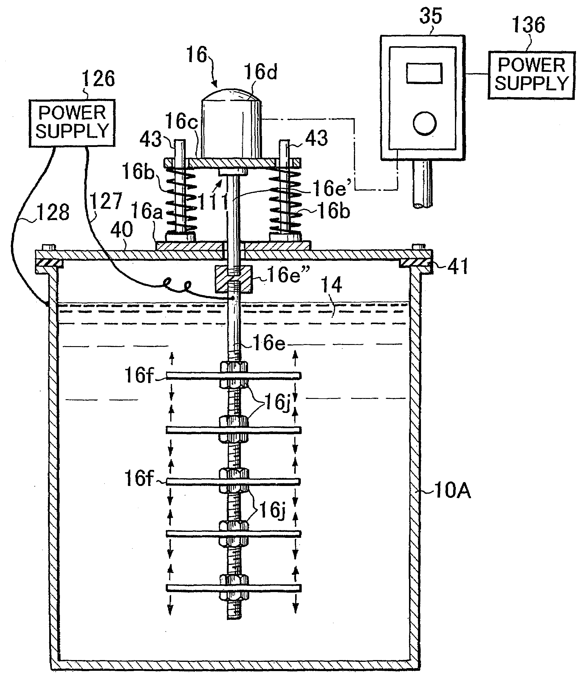
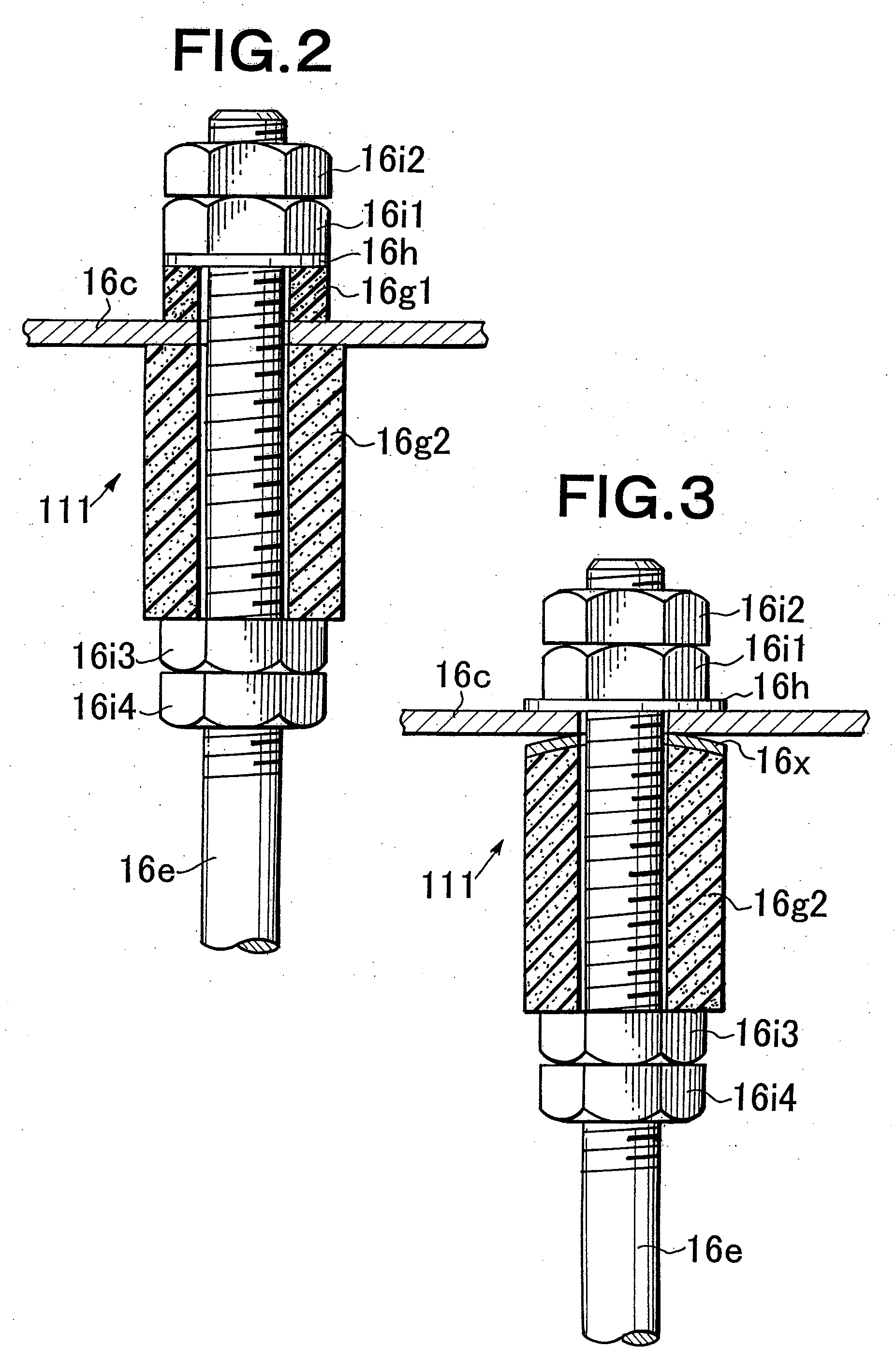
[0213]Insulated vibration-stirring apparatus: is installed on both sides of the inner tank member 61 of FIG. 34 as described in FIG. 16 and FIG. 17.

Vibration motor: 200 volts (3-phase)×150 watts, vibration frequency: 42 Hertz

Vibrating vane: Cathode side is titanium. Anode side is platinum plating on the titanium surface.

Processing power supply voltage: 4.5 volts

Processing current: 3.5 amperes

Treatment tank: W300×L700×H350 millimeters

Processing fluid: Using a tryptiquese growth medium the intestinal bacteria (colon bacillus) was cultured for 24 hours at 35° C. After propagation, a turbid bacteria medium of 60 liters of milk within the treatment tank “contained 22,000 colon bacillus per liter of milk”.

[0214]After irradiating with ultraviolet light, conducting power and vibration-stirring (agitation), the results as shown in the following table ...

second embodiment

Electrodeposition Painting

[0216]Cation electrodeposition coating of automotive parts was performed using the insulated vibration-stirring apparatus described in FIG. 21 and FIG. 22, as the insulated vibration-stirring apparatus 16 for the surface treatment apparatus (electrodeposition coating device) described in FIG. 23.

[0217]A tank made of steel with an inner lining of plastic was used as the treatment tank (electrodeposition tank) 10A. A processing liquid 14 (liquefied electrodeposition coating) consisting of synthetic fatty soluble emulsion, pigment paste, and water was filled into this tank A negative electrode hanger was affixed to the electrically insulated suspension conveyor 80 in the tank, The automotive part (processing product ART) was hung from it and used as the negative electrode. As shown in FIG. 21 and FIG. 22, the insulated vibration-stirring apparatus contains two vibrating rods and, a vibrating vane of titanium plated with platinum (thickness 0.5 mm, D1=250 mm an...

third embodiment

Electrodeposition Coating

[0223]The insulated vibration-stirring apparatus of the third embodiment does not use electrode support vanes. The vibrating vane have a thickness of 0.5 millimeters, D1=250 mm and D2=170 mm as shown in FIG. 12 and a tilt angle α=15 degrees as shown in FIG. 11. A titanium lath web electrode plate (electrode member) with platinum plating was inserted between all insulated vibration-stirring apparatus and automotive part as described using FIG. 26. These electrode plates were anodes of the same polarity utilizing vibrating rods and vibrating vanes of the vibration-stirring apparatus. The gap between the tip of the vibrating vane and the lath web electrode plate was 50 millimeters. The minimum distance between the lath web electrode plate and automotive part was 100 millimeters. In other words, the positional relationship of the insulated vibration-stirring apparatus, the lath web electrode plate and the processed part was the same as shown in FIG. 28.

[0224]Ele...


PUM

PropertyMeasurementUnit
frequencyaaaaaaaaaa
current densityaaaaaaaaaa
thicknessaaaaaaaaaa

Abstract

An insulated vibration-stirring apparatus comprising: a vibration generating means containing a vibration motor and a vibrating member attached to that motor, and a vibrating rod attached by an installation piece to allow vibration lined with the vibration generating means, and vibrating vanes installed on this vibrating rod. An electrical insulation area made from hard rubber is installed on a section nearer to the installation section to the installation piece than the section where the vibrating vanes are mounted on the vibrating rod. An electrical line is connected to the lower section of the vibrating rod on the electrical insulation area side where the vibrating vanes are installed. This electrical line conducts power to the vibrating vanes by way of the lower section of the vibrating rod. A power supply applies a voltage across the lower section of the vibrating rod and vibrating vanes and treatment tank by way of the electrical lines, and while applying power to the processing liquid within the treatment tank, the insulation vibration stirring apparatus vibrates and stirs the processing liquid.

Description

[0001]This is a division of U.S. patent application Ser. No. 10 / 481,198 filed Dec. 18, 2003 entitled “Vibratingly Stirring Apparatus, and Device and Method for Processing Using the Stirring Apparatus” which is a 371 of PCT / JP02 / 06217 filed on Jun. 21, 2002, published on Jan. 3, 2003 under publication number WO 03 / 000395 A1 and claims priority benefits of Japanese Patent Application No. 2001-192050 filed Jun. 25, 2001 and Japanese Patent Application No. 2001-245611 filed Aug. 13, 2001, the disclosures of which are hereby incorporated by reference.BACKGROUND OF THE INVENTION[0002]1. Field of the Invention[0003]The present invention relates to a novel vibration stirring apparatus incorporating functions of both an electrode and a cooling means, and to a device and method for processing liquids or products utilizing a vibration stirring apparatus. The present invention is for example ideal for surface treatment of products of all types by electrolysis.[0004]2. Description of Related Art...

Claims


Application Information

Patent Timeline
Patent Type & Authority Applications(United States)
IPC IPC(8): B01F11/00B01F11/02C25D5/00C25D17/00C25D21/10
CPCB01F11/0082C25D17/00C25D17/004C25D5/20C25D21/10C25D5/623C25D5/617C25D5/611B01F31/441B01F31/00
Inventor OMASA, RYUSHIN
Owner JAPAN TECH CO LTD (JP)
Why Eureka
Try Eureka