

Antireflective film, polarizing plate and image display device
a technology of anti-reflective film and polarizing plate, which is applied in the field of anti-reflective film, can solve the problems of adversely affecting transparency, hardness and durability, and achieve the effects of preventing dust adhesion, excellent anti-static properties, and high adhesion
- Summary
- Abstract
- Description
- Claims
- Application Information
AI Technical Summary
Benefits of technology
Problems solved by technology
Method used
Image

Examples
example 1
[0311]Antireflective film Samples 101 to 107 having the compositions shown in Table 1 were made, and evaluated by the methods described above.
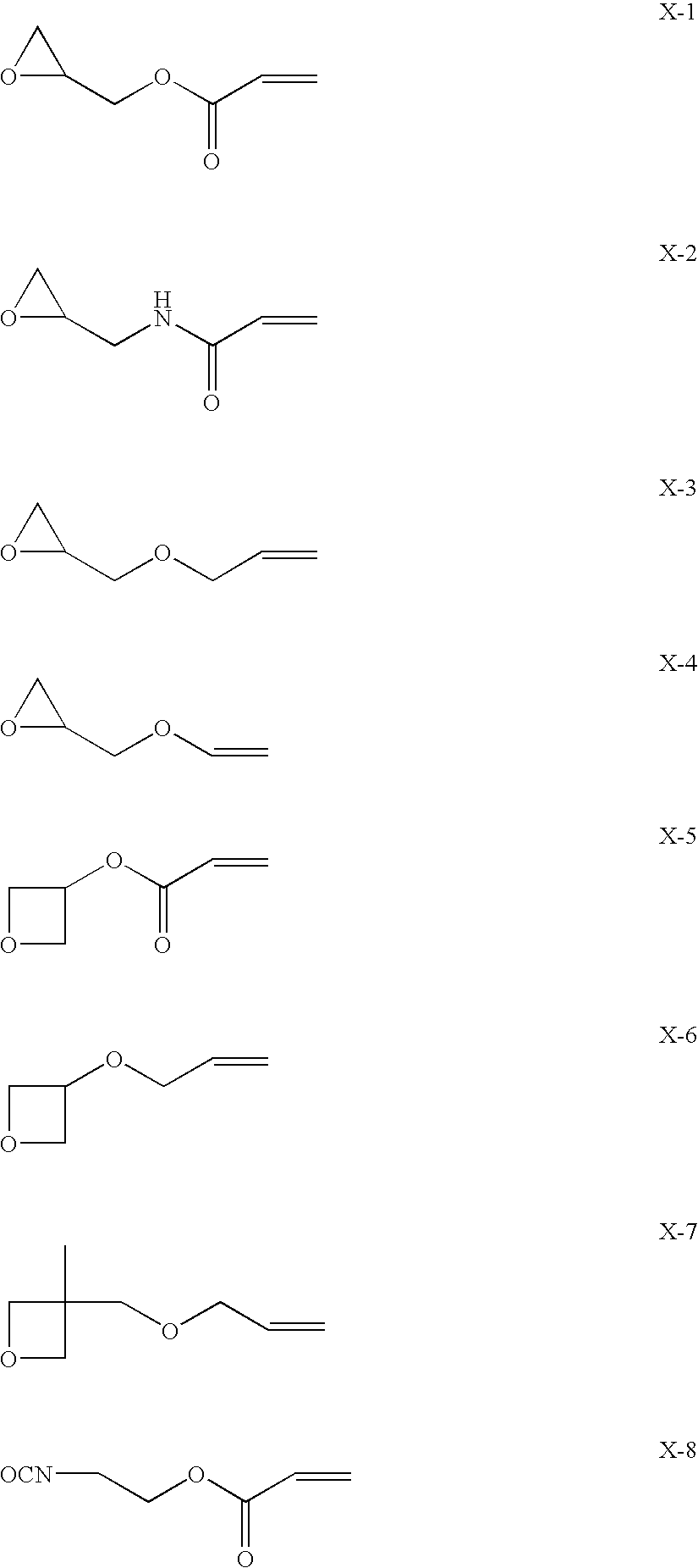
TABLE 1Conductive LayerCross-linkingLowSteelHardTransparentSite-FormingRefractiveIntegratedWoolCoatingConductiveCompound (AmountIndexReflectanceAbrasionSampleLayerLayeradded)Layer(%)logSRAdhesionResistancenote101H-1C-1X-1L-12.610.3B3Invention(6.4 g)102″″X-2″2.610.2B3Invention(6.4 g)103″″X-5″2.610.3A4Invention(6.4 g)104″″X-8″2.610.2A5Invention(7.1 g)105″″nothing″2.610.3D1ComparativeExample106nothing″nothing″2.610.3D1ComparativeExample107nothing″X-5″2.610.3B3Invention(6.4 g)
[0312]The antireflective films according to the invention were able to have sufficient surface resistance values by effects of the transparent conductive material, and delivered excellent adhesion and steel wool abrasion resistance by effects of the cross-linking site-forming compounds. The surface resistance value in the comparative example was equivalent to those in the inv...
example 2
[0313]Antireflective film Samples 201 to 205 having the compositions shown in Table 2 were made, and evaluated by the methods described above.
TABLE 2Conductive LayerCross-linkingLowSteelHardTransparentSite-FormingRefractiveIntegratedWoolCoatingConductiveCompound (AmountIndexReflectanceAbrasionSampleLayerLayeradded)Layer(%)logSRAdhesionResistancenote201H-2C-1X-1L-21.49.8B3Invention(6.4 g)202″C-2X-1″1.49.8A4Invention(6.4 g)203″C-3X-1″1.49.8A4Invention(6.4 g)204″″X-8″1.49.8A5Invention(7.1 g)205″″nothing″1.410D1ComparativeExample
[0314]The antireflective films according to the invention were able to have sufficient surface resistance values by effects of the transparent conductive materials, and delivered excellent adhesion and steel wool abrasion resistance by effects of the cross-linking site-forming compounds. The samples 202 to 204 in particular, wherein the polymer dopants having nonionic functional groups were used, made further improvements in adhesion and steel wool abrasion resi...
example 3
[0315]Antireflective film Samples 301 to 303 having the compositions shown in Table 3 were made, and evaluated by the methods described above. As to the conditions for curing the low refractive index layers used in the present example, however, 10 minutes' heating at 110° C. was not conducted.
TABLE 3Conductive LayerCross-linkingLowHardTransparentSite-FormingRefractiveIntegratedSteel WoolCoatingConductiveCompound (AmountIndexReflectanceAbrasionSampleLayerLayeradded)Layer(%)logSRAdhesionResistancenote301H-3C-1Oligomer a-1L-31.39.8A5Invention(23.5 g)302″″Oligomer a-2″1.39.8A5Invention(22.0 g)303″″nothing″1.39.9D1ComparativeExample
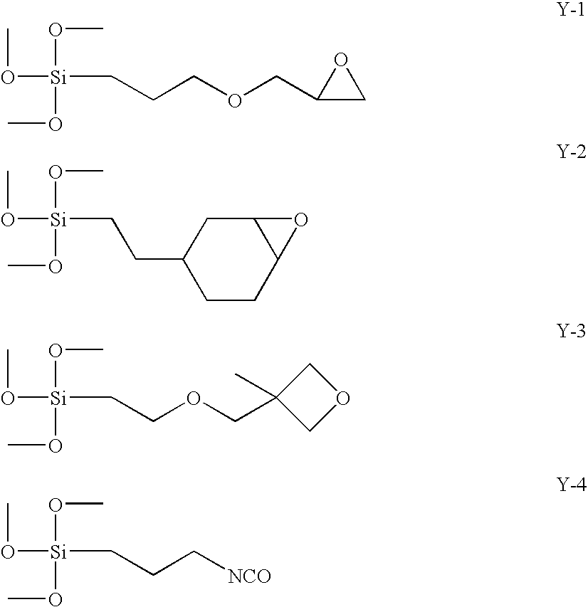
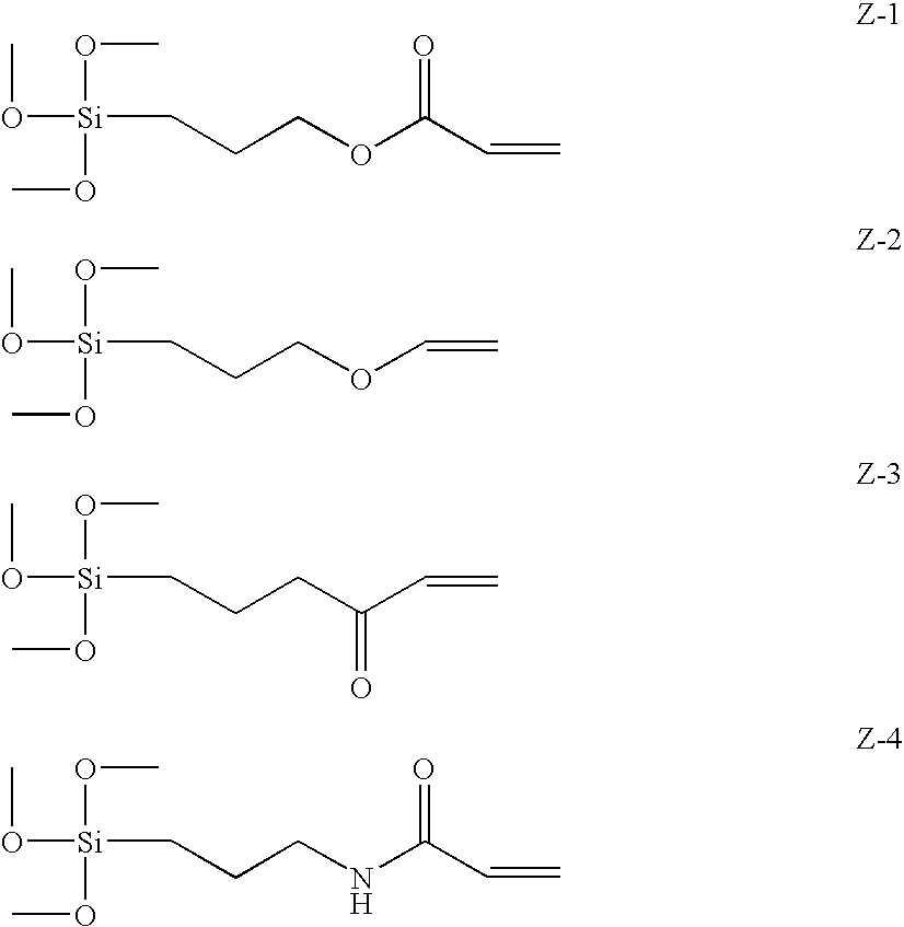
[0316]The samples 301 and 302, which each used as the cross-linking site-forming compound the oligomer sol formed from a mixture of the compounds represented by formulae (1) and (2) according to the invention, were able to have sufficient surface resistance values by effects of the transparent conductive material, and rated highest in adhesion and steel wool a...
PUM
| Property | Measurement | Unit |
|---|---|---|
| refractive index | aaaaa | aaaaa |
| refractive index | aaaaa | aaaaa |
| refractive index | aaaaa | aaaaa |
Abstract
Description
Claims
Application Information