Heat exchanger for cooling reaction gas

a technology of reaction gas and heat exchanger, which is applied in the direction of machines/engines, lighting and heating apparatus, hydrocarbon oil treatment products, etc., can solve the problems of reducing the overall pressure loss of the reaction gas in the cooler, increasing the yield of ethylene, propylene, butadiene, etc., and reducing the structural build-up of the reaction gas. , the effect of reducing the build-up

Active Publication Date: 2008-05-29
BORSIG AG
View PDF12 Cites 38 Cited by
  • Summary
  • Abstract
  • Description
  • Claims
  • Application Information

AI Technical Summary

Benefits of technology

[0012]That partial chamber of the heat exchanger disposed on the gas inlet or introduction side for the reaction gas serves as an evaporator and cools the reaction gas to nearly the boiling temperature of the boiling water. Subsequently, the reaction gas passes into the partial chamber that is disposed on the gas outlet or discharge side for the reaction gas and that serves as a preheater, where the reaction gas is further cooled by the cooler feed or supply water to significantly below the boiling temperature of water. As a result, the cooling of the reaction gas is on the whole more effective. The feed water that thereby heats up is either supplied to the steam drum, where it is heated to the boiling tempe

Problems solved by technology

As a result, the overall pressure loss of the reaction gas in the cooler is reduced, which not only increases the yiel

Method used


Image

  • Heat exchanger for cooling reaction gas
  • Heat exchanger for cooling reaction gas

Examples


Embodiment Construction

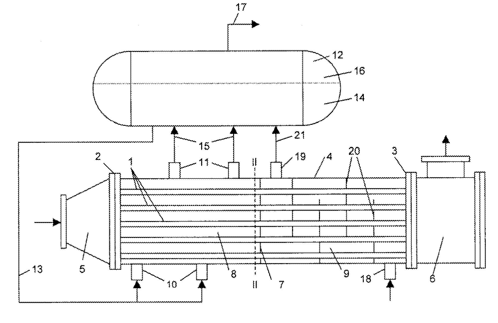
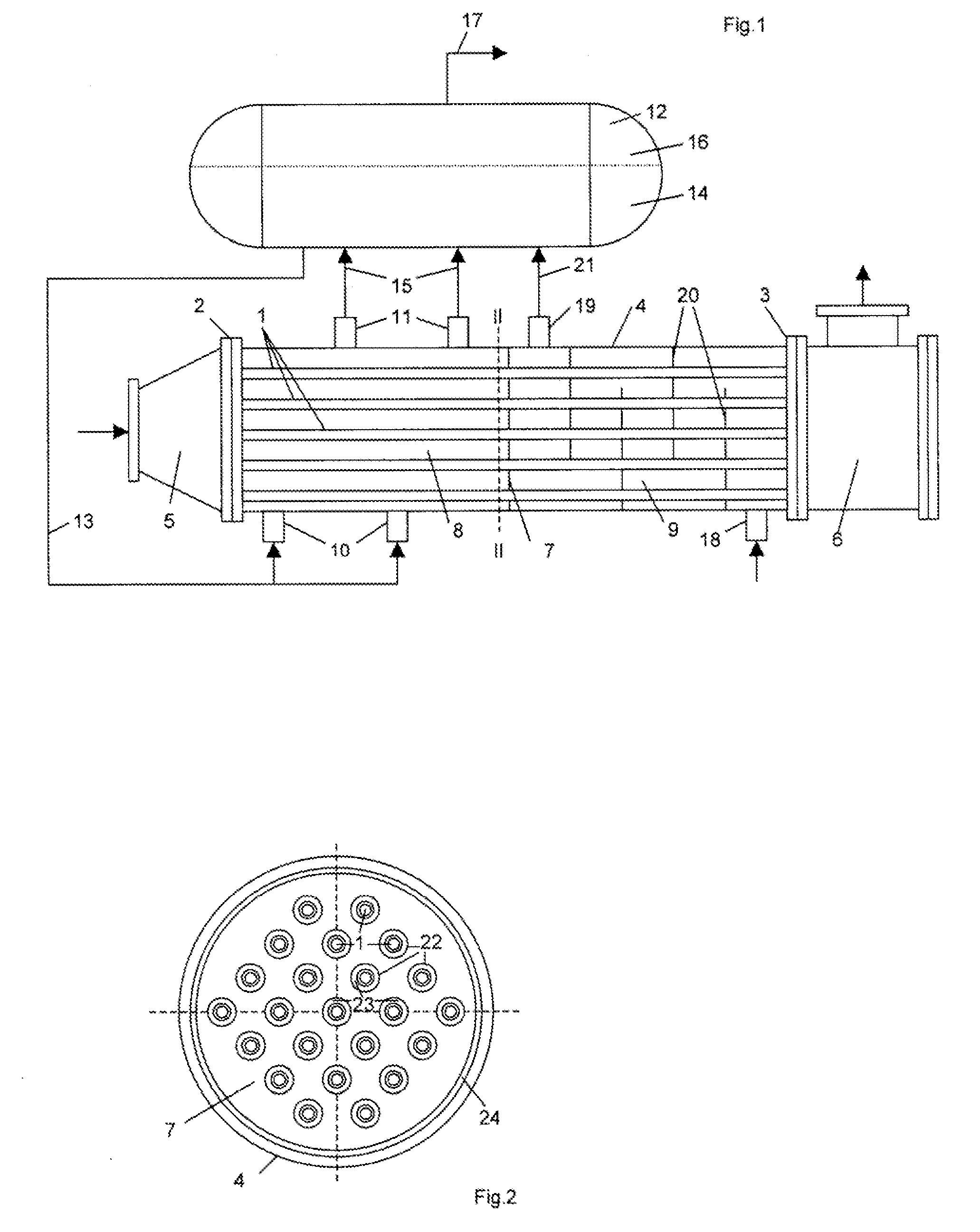
[0016]Referring now to the drawing in detail, the illustrated heat exchanger serves for the cooling of reaction gas in an ethylene plant. The heat exchanger is comprised of a tube bundle of straight heat exchanger tubes 1, which are held in respective tube plates 2, 3 at both ends of the tube bundle. In the drawing, only a few of the heat exchanger tubes 1 are shown to facilitate illustration. Bores extend through each of the tube plates 2, 3; one of the heat exchanger tubes 1 is inserted into each of the bores and is welded to the tube plates 2, 3 via a weld seam. The tube bundle is surrounded by an external jacket or shell 4, which together with the respective tube plates 2, 3 delimits an inner chamber through which flows a coolant or cooling agent.

[0017]Respectively adjoining the tube plates 2, 3 on the gas introduction side and on the gas discharge side is an end chamber, namely the inlet chamber 5 and the discharge chamber 6. Each of the inlet chamber 5 and discharge chamber 6 ...


PUM


Abstract

A heat exchanger for cooling reaction gas, wherein the respective ends of heat exchanger tubes, through which the reaction gas flows, are inserted in a respective tube plate and are surrounded by a jacket, at the two ends of which are provided a respective end chamber that is partially delimited by one of the tube plates and serves for the supply and withdrawal of the reaction gas; water, as cooling agent, flows through the inner chamber of the heat exchanger that is surrounded by the jacket and that is divided by a partition, extending perpendicular to the heat exchanger tubes, which extend through it, into two partial chambers disposed one after the other in the direction of flow of the reaction gas, each partial chamber being provided with its own supply connectors and outlet connectors for the cooling agent; boiling water flows through the partial chamber that is disposed on the inlet side for reaction gas and that is connected via a supply line and withdrawal lines with a water/steam drum; feed water flows through the partial chamber that is disposed on the outlet side for the reaction gas and that is connected via a withdrawal line with the water/steam drum. The partition between the two partial chambers permits the passage of the cooling agent that flows in the inner chamber of the heat exchanger.

Description

[0001]The instant application should be granted the priority date of 24 Nov. 2006, the filing date of the corresponding German patent application DE 10 2006 055 973.8.BACKGROUND OF THE INVENTION[0002]The present invention relates to a heat exchanger for cooling reaction gas in an ethylene plant. Within an ethylene plant, pyrolysis or ethylene cracking or disassociation furnaces form the precursors or key components for the manufacture of the base materials ethylene, propylene, butadiene, and others for the plastics industry. Used as starting material are saturated hydrocarbons, principally ethane, propane, butane, natural gas, naphtha, or gas oil. The conversion of the saturated hydrocarbons into unsaturated hydrocarbons takes place in the cracking tubes of the cracking furnace, and in particular at inlet temperatures of 500-680° C. and discharge temperatures of 775-875° C. in a pressure range of 1.5-5 bar.[0003]In subsequent reaction gas coolers disposed at the outlet of the cracki...

Claims


Application Information

Patent Timeline
IPC IPC(8): F28F9/22
CPCC10G2400/20F01K3/188F22B1/1838F22B1/1884F22B9/10F28F2009/226F28D7/0066F28D7/0091F28D7/1607F28D2021/0075F28F9/22F22B37/40
Inventor BIRK, CARSTEN
Owner BORSIG AG
Why Eureka
Try Eureka