
Straddle carrier having a low-emission and low-maintenance turbine drive

Inactive Publication Date: 2008-05-29
NOELL MOBILE SYST
View PDF8 Cites 24 Cited by
  • Summary
  • Abstract
  • Description
  • Claims
  • Application Information

AI Technical Summary

Benefits of technology

[0018]It is therefore an object of the invention to eliminate the disadvantages of the known prior art, and to develop a straddle carrier that has a drive system that makes do with clearly less maintenance and replacement, causes fewer harmful exhaust gases and noise, is gentle on the sensitive electronics because of its quiet, vibration-free operation, and keeps the expenditure for this within reasonable limits.
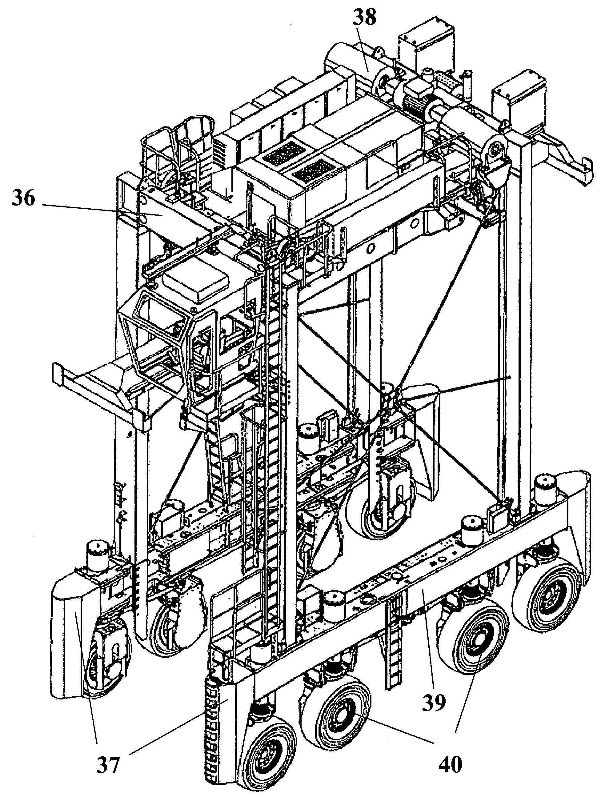
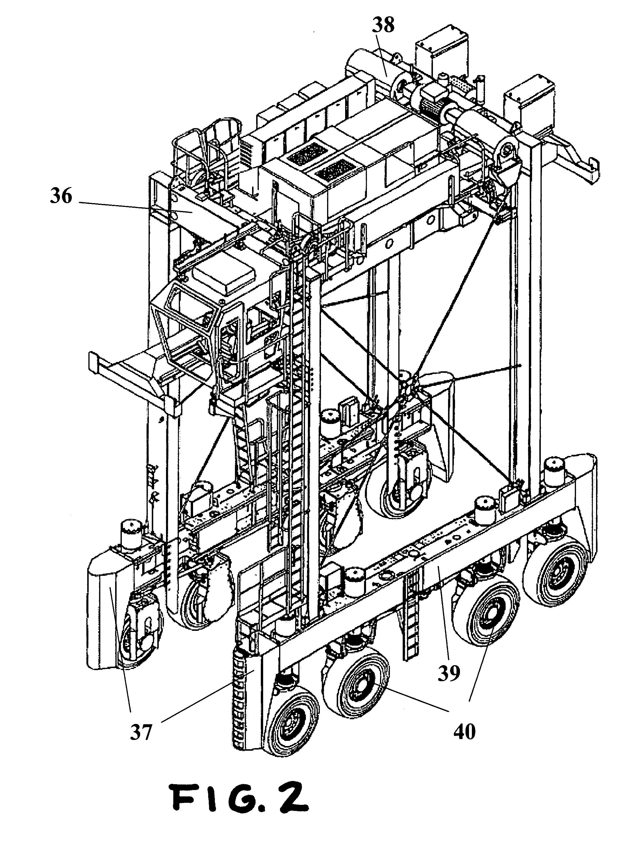
[0019]This task is accomplished by means of a straddle carrier having an electric drive system, consisting of a lower and an upper frame, which are connected with one another by means of supports. A lifting mechanism with hoists is disposed on the upper frame, and the lower frame consists of chassis carriers having electrically driven wheels and a power generation unit that feeds its generated electric power into a direct voltage intermediate circuit, to which current inverters for supplying the travel, lifting, and auxiliary motors are connected. The power generation unit represents a micro gas turbine having an attached power generator, the power of which is passed to the travel, lifting, and auxiliary motors, and a separate regulator disposed on the micro gas turbine, which regulates the operating variables of power, speed of rotation, and temperature of the turbine individually, together, or in combination, to achieve reference values that can be predetermined. There are current inverters that can be regulated disposed ahead of the chassis, auxiliary, and lifting mechanism motors and an electronic power management of the straddle carrier is disposed on the regulator for the power generation unit, which control coordinates the power and voltage of the power generation unit and drive motors with one another. Appropriate reference values are provided to the regulator of the power generation unit and the current inverters of the drive motors, which can be regulated, by the power management. The most different load demands of travel and lifting mechanism drives occur superimposed on one another. There is an electric power storage unit disposed on a bus bar of the intermediate circuit, directly or indirectly, which unit evens out load variations and saves braking and lowering power.
[0023]Such regulation is possible in that the speed of rotation and the inlet temperature of the turbine are detected by way of sensors and passed to an electronic control device, the microprocessor, which then controls a fuel regulation valve in order to keep the turbine in a narrow optimal speed of rotation and temperature range by means of setting the amount of fuel. In this connection, the same electric power always has to be taken off from the turbine generator, as well, and for this purpose, the regulation system controls power electronics, e.g. an IGBT current inverter. A power storage unit such as a rechargeable battery must therefore balance out the load variations of the electric power given off for consumption, as compared with the constantly produced turbine power.
[0024]A further development of this regulation system consists in no longer keeping the generated turbine power constant, but rather regulating it to the required load when load variations occur, by means of adjusting the speed of rotation, whereby nevertheless, the optimal turbine inlet temperature is maintained. This has the advantage that even in partial load operation, only slight losses in the degree of effectiveness occur. A power storage unit, e.g. a buffer battery, takes over the electric load difference only part of the time, if load variations occur, until the turbine power has been adjusted. If the required turbine power is to be increased by increasing the speed of rotation, for instance, the regulator temporarily decreases the electric power output of the generator by controlling a current inverter, in other words relieves the stress on the turbine, so that it can run up to the new speed of rotation at a constant temperature, and in turn increases the power output of the buffer battery, until the new speed of rotation and power have been reached. Then, the entire power needed is taken from the generator once again.
[0025]From this, it is evident that such a micro turbine power unit can only function in a usable manner together with the installed power electronics, a digital regulation system, and a storage battery. Without these electronics, the generator current that is generated, which has a frequency of over 1600 Hertz, could not supply any of the usual consumers, and the turbine could not be regulated in stable manner. Only power and regulation electronics, together with the battery, make it possible not to stall the turbine in case of load variations of the electric power that is taken off, or to accelerate it to dangerously high speeds of rotation.
[0030]Finally, it is advantageous to supply the auxiliary drives, such as hydraulic pumps for steering, brakes, and spreader, the alternator for charging the batteries and supplying the on-board network, for example a 24V DC network, and the air conditioning of the driver's cabin, which were previously driven directly and mechanically by a diesel engine, with power from the micro turbine.

Problems solved by technology

The integration relates both to the power electronics and to the control and regulation electronics, and the technical effort for this remains low.

Method used


Image

  • Straddle carrier having a low-emission and low-maintenance turbine drive
  • Straddle carrier having a low-emission and low-maintenance turbine drive
  • Straddle carrier having a low-emission and low-maintenance turbine drive

Examples


Embodiment Construction

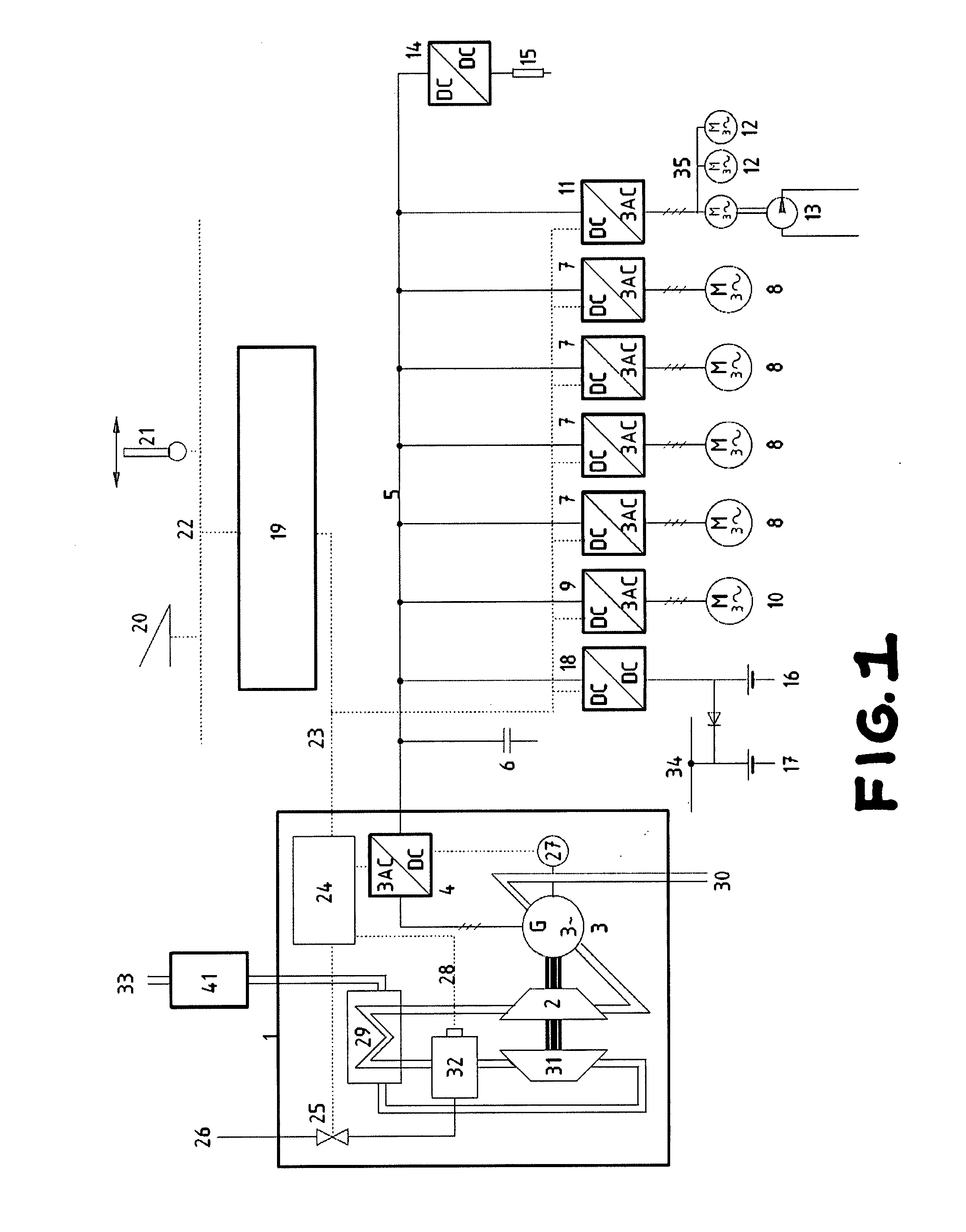
[0034]As shown in FIG. 1, the medium-frequency rotary current from generator 3 of micro turbine 2 is fed directly into a direct current intermediate circuit 5 of the straddle carrier, by way of a two-quadrant current inverter 4 that can be pulse-width-modulated and regulated. Current inverters 7, 9, 11 for chassis motors 8, lifting mechanism motor 10, and auxiliary motors 12 are connected directly with it, and brake resistors 15 are connected by way of brake choppers 14. The two batteries (a starter battery 16, and a battery 17 for the 24V DC on-board network, to supply the electronics and the lighting, are also connected with direct current intermediate circuit 5, by way of a DC / DC converter 18 (high / low regulator).

[0035]In addition to the usual auxiliary motors for the cooling pumps of the travel drives, the fan of the lifting mechanism drive, and other smaller motors and consumers, pump motor 13 of a small hydraulic station, which generates the hydraulic pressure for steering, br...


PUM


Abstract

A straddle carrier having an electric drive system, consisting of a lower and an upper frame, which are connected with one another by means of supports. A lifting mechanism with hoists is disposed on the upper frame, and the lower frame consists of chassis carriers having electrically driven wheels, and a power generation unit that feeds its generated electric power into a direct voltage intermediate circuit, to which current inverters for supplying the travel, lifting, and auxiliary motors are connected. The power generation unit represents a micro gas turbine having an attached power generator, the power of which is passed to the travel, lifting, and auxiliary motors. The straddle carrier can be produced at low weight and maintained under advantageous conditions. Furthermore, the straddle carrier can be operated under environmentally friendly conditions.

Description

CROSS-REFERENCE TO RELATED APPLICATIONS[0001]This application claims priority under 35 U.S.C. §119 of German Patent Application No. 10 2006 055 749.2, filed on Nov. 25, 2006.BACKGROUND OF THE INVENTION[0002]1. Field of the Invention[0003]The invention relates to a straddle carrier, also known as a portal lift truck, having an electric drive system. The straddle carrier according to the invention can be used worldwide in ocean harbors, container transport terminals, for transporting and stacking containers, and is particularly well suited where diesel-operated vehicles cannot easily be operated, due to their noise, exhaust gases, lubricant oil, and need for regular maintenance.[0004]2. The Prior Art[0005]Diesel-electric drive systems for such straddle carriers are known. In general, they consist of a diesel engine having a generator for generating electric power, a direct current intermediate circuit, and several current inverters that can be regulated and are connected to it, for su...

Claims


Application Information

Patent Timeline
IPC IPC(8): B60L11/02B60L11/12B60L50/10B60L50/13B60L50/15B60L50/16
CPCB60L11/08B60L2270/145Y02T10/7077Y02T10/648B60K3/04B60L11/14B66C13/22B66C19/007B60K6/46B60Y2200/40B60Y2200/66B60Y2400/431Y02T10/70B60L1/003B60L7/14B60L7/22B60L11/005B60L2200/42B60L2210/30B60L2210/40B60L2220/12B60L2240/423B60L2240/427B60L2240/441B60L2240/443B60L2240/445B60L2270/12B60L2270/142Y02T10/646B60L50/13B60L50/16B60L50/40B66C13/18Y02T10/62Y02T10/64Y02T10/7072Y02T10/72
Inventor BAUER, REINHARD
Owner NOELL MOBILE SYST
Learn More