Edge seals for composite structure fuel tanks

a fuel tank and composite structure technology, applied in the direction of synthetic resin layered products, mechanical equipment, chemistry equipment and processes, etc., can solve the problems of inefficient application to commercial transportation aircraft, inconvenient installation, and relatively complicated tank geometry

Active Publication Date: 2008-06-05
THE BOEING CO
View PDF12 Cites 66 Cited by
  • Summary
  • Abstract
  • Description
  • Claims
  • Application Information

AI Technical Summary

Benefits of technology

[0019]FIG. 5 is a fragmentary, cross sectional view of an end of the cut edge but showing the edge wrap covering the end of the spar.
[0020]FIG. 6 is a simplified flow chart showing the basic steps in applying the edge seal of the present invention.

Problems solved by technology

Various solutions have been proposed for mitigating the risk of fuel tank ignition, but each has limitations and none has been entirely successful.
For example, bladders have been employed to isolate fuel within tanks from the effects of an ignition event caused by failure of the fuel tank structure, however this solution requires relatively complicated tank geometry and is inefficient when applied to commercial transport aircraft.
Another solution involves of the use of a completely metallic internal structure for the fuel tank, but this approach is both inefficient from a strength and stiffness-to-weight standpoint, and is expensive relative to other potential solutions.
Prior to trimming, the carbon fibers are sealed by the epoxy resin within the laminate, but cutting of the laminate during the edge trimming process results in the carbon fibers being exposed at the cut edges.
When subjected to a high energy electrical charge such as that resulting from a lightning strike, and result in sparking between the fibers, or the release of highly energized particles which have the potential to ignite fuel.
The application of such sealants requires experienced personnel and is labor intensive in terms of both the sealant application and subsequent in-service inspection.
Moreover, these sealants must be applied after the fabrication of the fuel tank structure is completed since the sealant layers are relatively fragile and thus subject to damage caused by handling or assembly of tank substructures.
Another drawback of polysulfide-based sealants is that failures in the sealant coating are difficult, or sometimes impossible to inspect.
This detection problem is due in part, to the fact that polysulfide-based sealants are opaque, and thus visually mask underlying bonding defects or defects in the composite structure.
As a result, failure of polysulfide-based sealants can result in latent defects during in-service maintenance and inspections.
Another potential solution to the problem of reducing the risk of fuel tank ignition involves designing composite fuel tanks without the use of internal cut laminate edges, however this approach generally results in highly inefficient fuel tank designs from a fuel capacity to weight standpoint.

Method used


Image

  • Edge seals for composite structure fuel tanks
  • Edge seals for composite structure fuel tanks
  • Edge seals for composite structure fuel tanks

Examples


Embodiment Construction

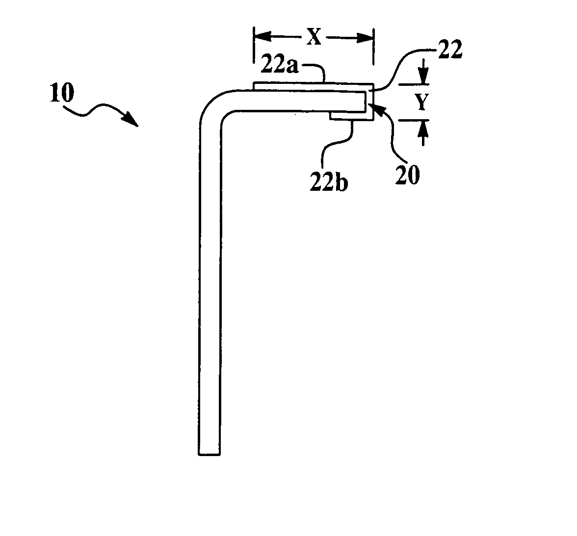
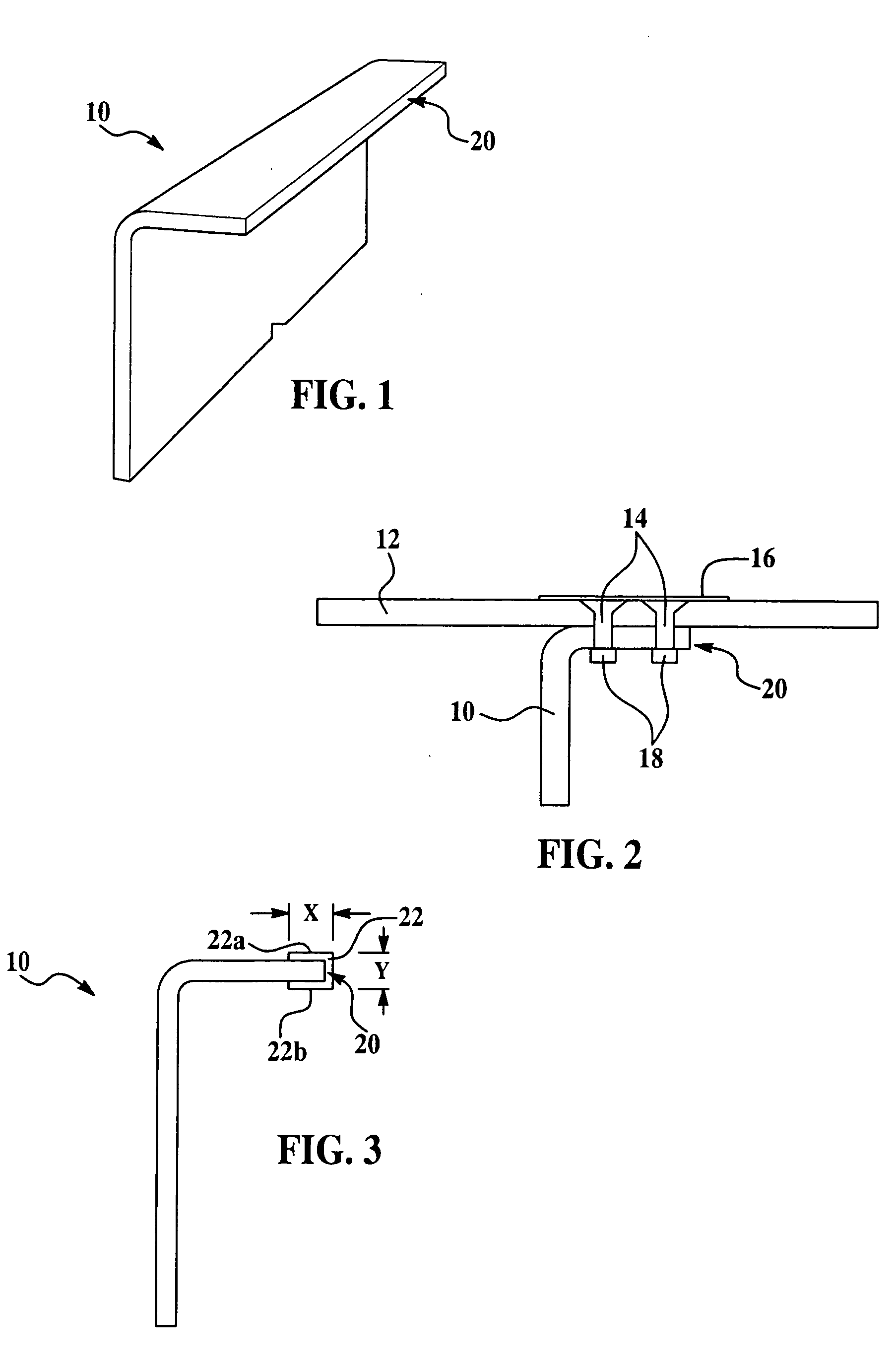
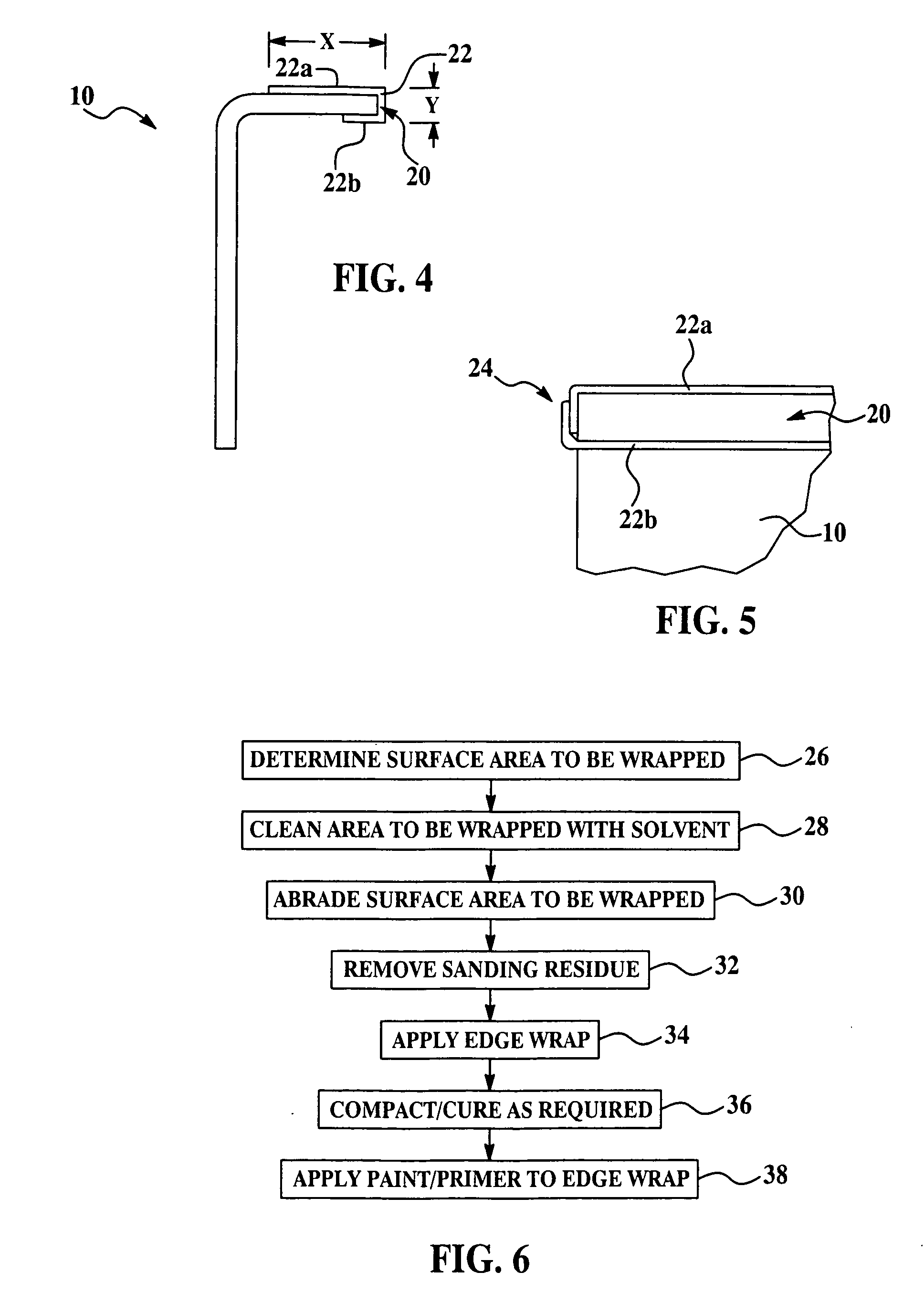
[0021]Referring first to FIGS. 1 and 2, a variety of carbon fiber reinforced polymer composite (CFRP) structural members are commonly employed in aircraft construction, such as a structural spar member 10 which is used to support numerous types of structures. For example, CFRP structural members like the spar 10 are used to fabricate and mount fuel tanks (not shown) in an aircraft. In the illustrated embodiment, the spar 10 is secured to and supports a skin 12, using fasteners 14, which pass through a copper plate 16 forming part of an electrical current diversion system, and are held in place by fastening collars 18. It should noted here that although an L-shaped spar has been selected to illustrate the principals of the invention, a wide variety of other forms of structural members are suitable for use with the present invention, including C-shaped spars which are more commonly used in constructing commercial aircraft.

[0022]The spar 10 is manufactured using conventional layup tech...


PUM

PropertyMeasurementUnit
thickaaaaaaaaaa
thickaaaaaaaaaa
thickaaaaaaaaaa

Abstract

The cut laminate edges of aircraft fuel tanks formed of carbon fiber reinforced polymers are sealed to prevent the exposure of carbon fibers to combustible fuel. The edge seal is produced from a prepreg form using a thermosetting resin matched to the characteristics of the resin used in the laminate. The prepreg form can be applied to the cut laminate edges either before or after the laminate is cured. The edge seal acts a dielectric layer that both electrically insulates the cut laminate edges from the fuel and mechanically contains energetic particles produced at the edges due to lighting strikes or other sources of electrical charges.

Description

BACKGROUND OF THE INVENTION[0001]1. Field of the Invention[0002]The present invention broadly relates to composite structure fuel tanks, especially for aircraft, and deals more particularly with a laminate edge construction that reduces the possibility of fuel combustion due to an electric charge.[0003]2. Description of the Related Art[0004]Federal regulations are imposing increasingly stringent standards for fuel tanks used on commercial aircraft. These regulations are directed toward reducing the possibility that fuel or fuel vapors in or around the tank might be ignited by ignition sources such as an electrical charge or spark produced by direct lightning strikes or other electrical currents reaching the fuel due to catastrophic structural failures.[0005]Various solutions have been proposed for mitigating the risk of fuel tank ignition, but each has limitations and none has been entirely successful. For example, bladders have been employed to isolate fuel within tanks from the ef...

Claims


Application Information

Patent Timeline
Patent Type & Authority Applications(United States)
IPC IPC(8): F17C1/02
CPCB29C63/0034B29C63/04Y10T156/1034B64D37/06B64D37/32B32B27/00B29C70/302
Inventor KOVACH, DANIEL J.STROMSLAND, KARI L.HEIDLEBAUGH, DIANE L.WARD, JOHN A.BROWN, ARLENE M.DABELSTEIN, DONALD K.
Owner THE BOEING CO
Why Eureka
Try Eureka