Optical-Scanning Microscope Examination Apparatus

a microscope and optical scanning technology, applied in the field of optical scanning microscope examination apparatus, can solve the problems of blurred image, difficult time-lapse observation for an extended period of time, and inability to acquire clear images, so as to reduce the burden on the living organism and reduce the projecting area

Inactive Publication Date: 2008-06-05
OLYMPUS CORP
View PDF10 Cites 20 Cited by
  • Summary
  • Abstract
  • Description
  • Claims
  • Application Information

AI Technical Summary

Benefits of technology

[0084]By doing so, during observation with another examination apparatus, such as the stereomicroscope apparatus, it is possible to prevent light reflected by the outer surface of the objective unit from interfering with the observation. The anti-reflection treatment may include black coating, matte processing, reflection-reduction coating, and so forth.
[0085]According to the present invention, because it is possible to adjust the focal position without moving a light-radiating end face of the focusing optical system, it is possible to perform observation while adjusting the focal position, with the light-radiating end face of the focusing optical system pressed against the subject. In such a case, by disposing the actuator, which moves the end portion of the light-transmitting member, the collimator optical system, or the pupil-projection optical system in the optical-axis direction, parallel to a plane including the optical axes before and after deflection, the actuator is prevented from protruding in the width direction, which reduces the projecting area on the subject; thus, an advantage is afforded in that it is possible to observe the subject from the opposite side of the focusing optical system from the subject, for example, such that it does not obstruct the stereomicroscope observation.
[0086]Moreover, according to the present invention, by separating the objective unit from the apparatus main body and keeping it inserted in the living organism, it is possible to perform observation without shifting the objective unit relative to the examination site when performing multiple observations of the same examination site of the living organism over time. Also, when attaching the apparatus main body to an objective unit remaining in the living organism, it is not necessary to rotate the objective unit, which allows the burden placed on the living organism to be reduced. Therefore, an advantage is afforded in that it is possible to perform in-vivo examination of biological tissue, such as cells or muscles, or various internal organs, such as the heart or liver, of mammals, including small laboratory animals, over a relative long period of time.

Problems solved by technology

However, the optical-scanning microscope examination apparatuses of the related art perform examination by positioning the objective lens at a predetermined distance relative to the subject, and are not assumed to perform examination of various internal organs of a small laboratory animal, such as a rat or mouse, while still alive (in vivo).
Thus, the optical-scanning microscope examination apparatuses of the related art cannot perform examination with the end surface of the objective lens in contact with the living organism, and unless another method is used, they suffer from the drawback that the image is blurred due to the pulsing, and it is not possible to acquire a clear image.
However, because the size of the objective lens disposed close to the examination site is large compared to the small laboratory animal, when examining the internal organs, it is necessary to make a large incision in the skin, muscle tissue or the like, or to form a large hole.
In this case, although examination is possible directly after making the incision in the tissue or directly after boring the hole, because substantial damage is done to the small laboratory animal, it is difficult to perform time-lapse observation for an extended period of time.
A method in which the incision is sutured directly after observation and an incision is made again at the next observation is conceivable; however, considering the damage done to the small laboratory animal, there is the drawback that it is difficult to perform observation under normal conditions as time passes.

Method used


Image

  • Optical-Scanning Microscope Examination Apparatus
  • Optical-Scanning Microscope Examination Apparatus
  • Optical-Scanning Microscope Examination Apparatus

Examples


second embodiment

[0167]Next, a scanning microscope examination apparatus 70 according to the present invention will be described below with reference to FIG. 10.

first embodiment

[0168]In the description of this embodiment, parts having the same configuration as those in the scanning microscope examination apparatus 1 described above are assigned the same reference numerals, and a description thereof is omitted.

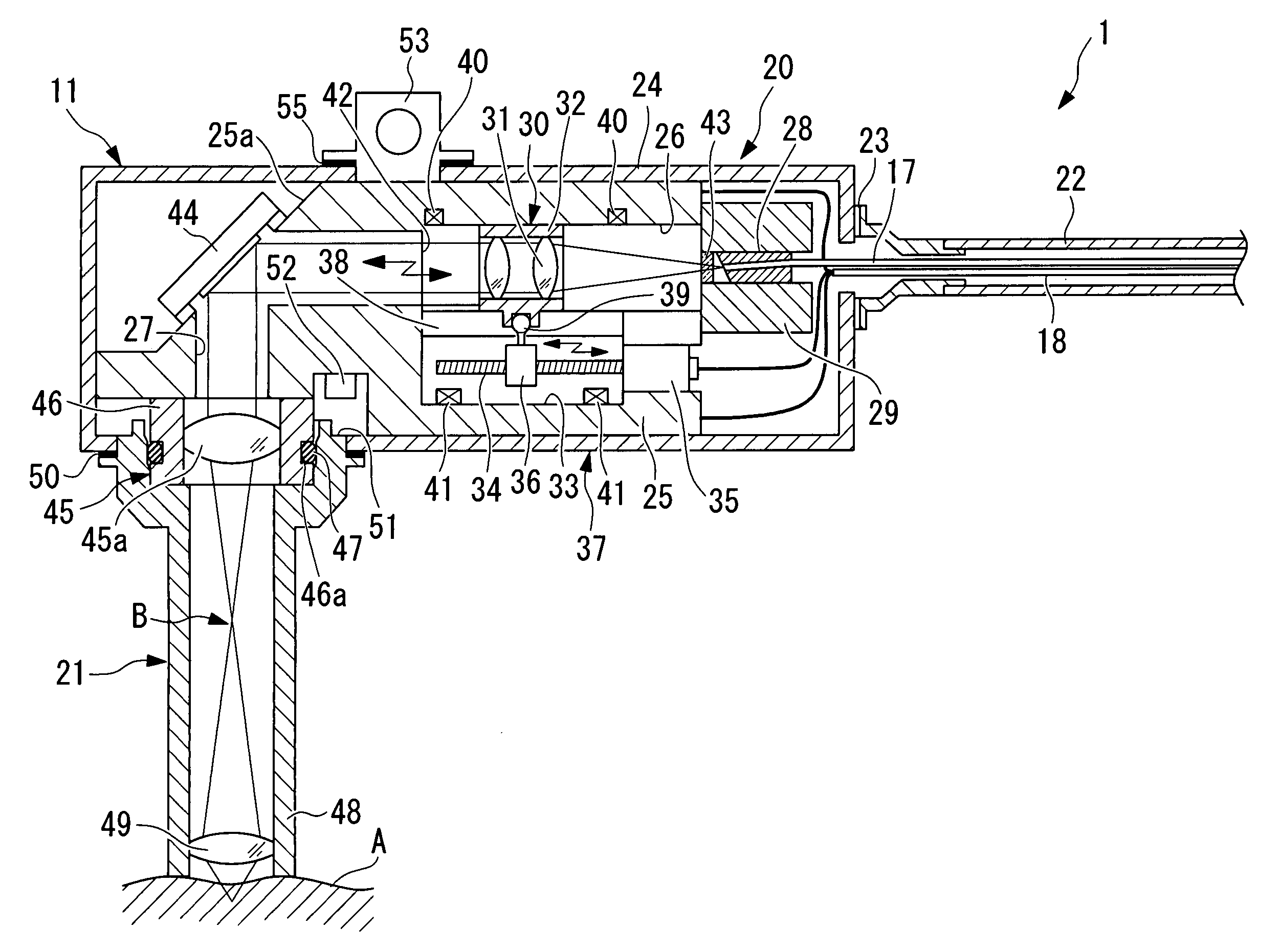
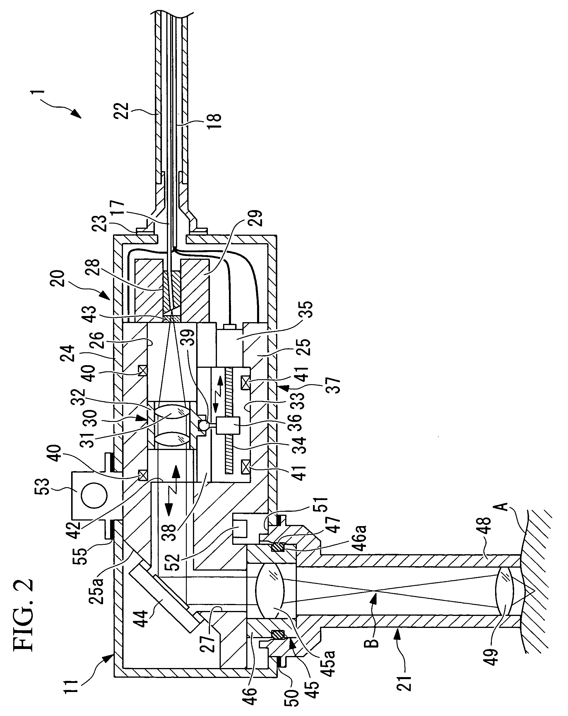
[0169]The scanning microscope examination apparatus 70 according to this embodiment differs from the first embodiment in that, whereas the scanning microscope examination apparatus 1 according to the first embodiment moves the collimator lens unit 30, the ferrule 28 (end portion of the light-transmitting member) to which the end of the optical fiber 17 is secured is moved in the optical-axis direction.

[0170]The ferrule 28 is disposed in such a manner that it can slide inside the first through-hole 26. In addition, an actuator 74 formed of a rod 71, a plunger 72 that makes the rod 71 project in the optical-axis direction, and a connecting member 73 connected to the rod 71 of the plunger 72 are provided. By engaging the connecting member 73 with a groo...

third embodiment

[0174]Next, a scanning microscope examination apparatus 80 according to the present invention will be described below with reference to FIGS. 11 and 12.

[0175]In the description of this embodiment, parts having the same configuration as those of the scanning microscope examination apparatus 1 and 70 according to the second embodiment are assigned the same reference numerals, and a description thereof is omitted.

[0176]Whereas the scanning microscope examination apparatuses 1 and 70 according to the first and second embodiments move the collimator lens unit 30 or the ferrule 28 in the optical axis direction, in the scanning microscope examination apparatus 80 according to this embodiment, the collimator lens unit 30 and the ferrule 28 are fixed to the chassis 20, and a pupil-projection lens unit 81 is moved along the optical-axis direction.

[0177]The pupil-projection lens unit 81, in which a lens barrel 81b, including a pupil-projection lens 81a, is disposed in such a manner as to be ca...


PUM


Abstract

A clear image having suppressed blurring due to pulsing is obtained by in-vivo examination of biological tissue or various internal organs of mammals, including small laboratory animals. The invention provides an optical-scanning microscope examination apparatus including a light source; a light-transmitting member for transmitting light from the light source; a collimator optical system for converting the transmitted light to a collimated beam; a beam-scanning unit for scanning the collimated beam on a subject; a focusing optical system for focusing the scanned beam onto the subject; a pupil-projection optical system; a light detector for detecting return light returning from the subject via the focusing optical system, the pupil-projection optical system, the beam-scanning unit, the collimator optical system, and the light-transmitting member; an actuator for moving the collimator optical system in an optical-axis direction; a control apparatus for controlling driving thereof; and a deflecting mechanism for deflecting the light issuing from the light-transmitting member in a direction intersecting the optical axis thereof, wherein the actuator is disposed in a space parallel to a plane including optical axes before and after deflection by the deflecting mechanism.

Description

TECHNICAL FIELD[0001]The present invention relates to an optical-scanning microscope examination apparatus.BACKGROUND ART[0002]As optical-scanning microscope examination apparatuses in the related art for performing magnified observation of a subject, there are those having the structures disclosed in Patent Document 1 and Patent Document 2. In these optical-scanning microscope examination apparatuses disclosed in Patent Documents 1 and 2, a lens driving mechanism is provided in an objective lens for rapidly aligning the focal position relative to the subject with an examination site.[0003]In addition, a laser-scanning confocal microscope is a known apparatus for examining cellular function and so on by illuminating a specimen such as a living organism with excitation light from the surface thereof and selectively detecting fluorescence produced from a predetermined depth position in the specimen (for example, see Patent Documents 3 and 4).[0004]This laser-scanning confocal fluoresc...

Claims


Application Information

Patent Timeline
Patent Type & Authority Applications(United States)
IPC IPC(8): G02B21/06A61B1/00A61B5/00G02B21/00G02B21/22G02B26/10
CPCA61B5/0059A61B2503/40G02B21/22G02B21/0036A61B5/0068
Inventor HARA, MITSUHIROTOSAKA, HIROSHIHORII, AKIHIROTANIKAWA, YOSHIHISA
Owner OLYMPUS CORP
Why Eureka
Try Eureka