Electronic Component and Electronic-Component Production Method
a technology of electronic components and production methods, applied in the direction of fixed capacitor details, feed-through capacitors, printed circuit non-printed electric components association, etc., can solve the problems of stray capacitance mismatching of the characteristic impedance near the outer electrodes, and reducing the distance between the outer electrodes, so as to prevent the noise of the noise, prevent the characteristic impedance from decreasing, and prevent the effect of stray capacitan
- Summary
- Abstract
- Description
- Claims
- Application Information
AI Technical Summary
Benefits of technology
Problems solved by technology
Method used
Image
Examples
first embodiment
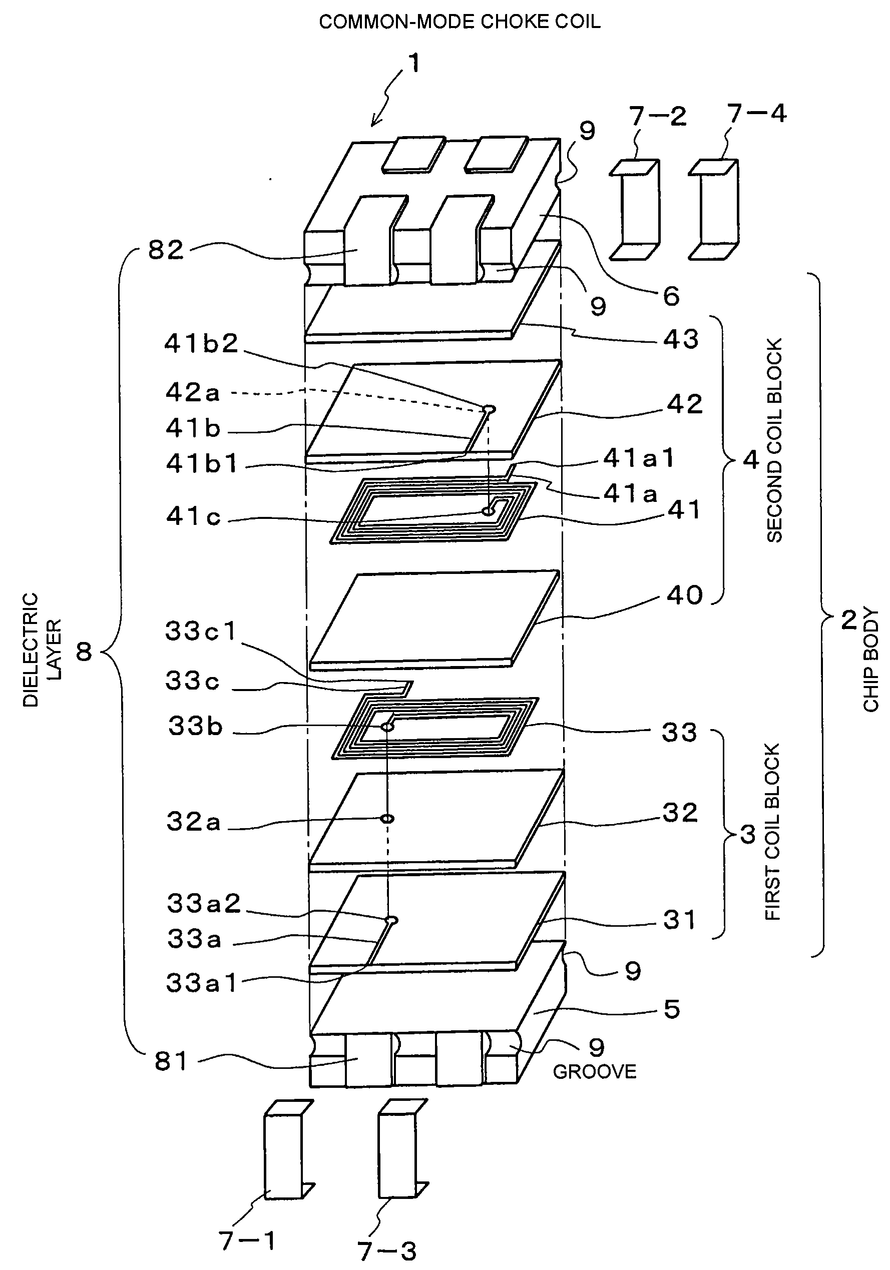
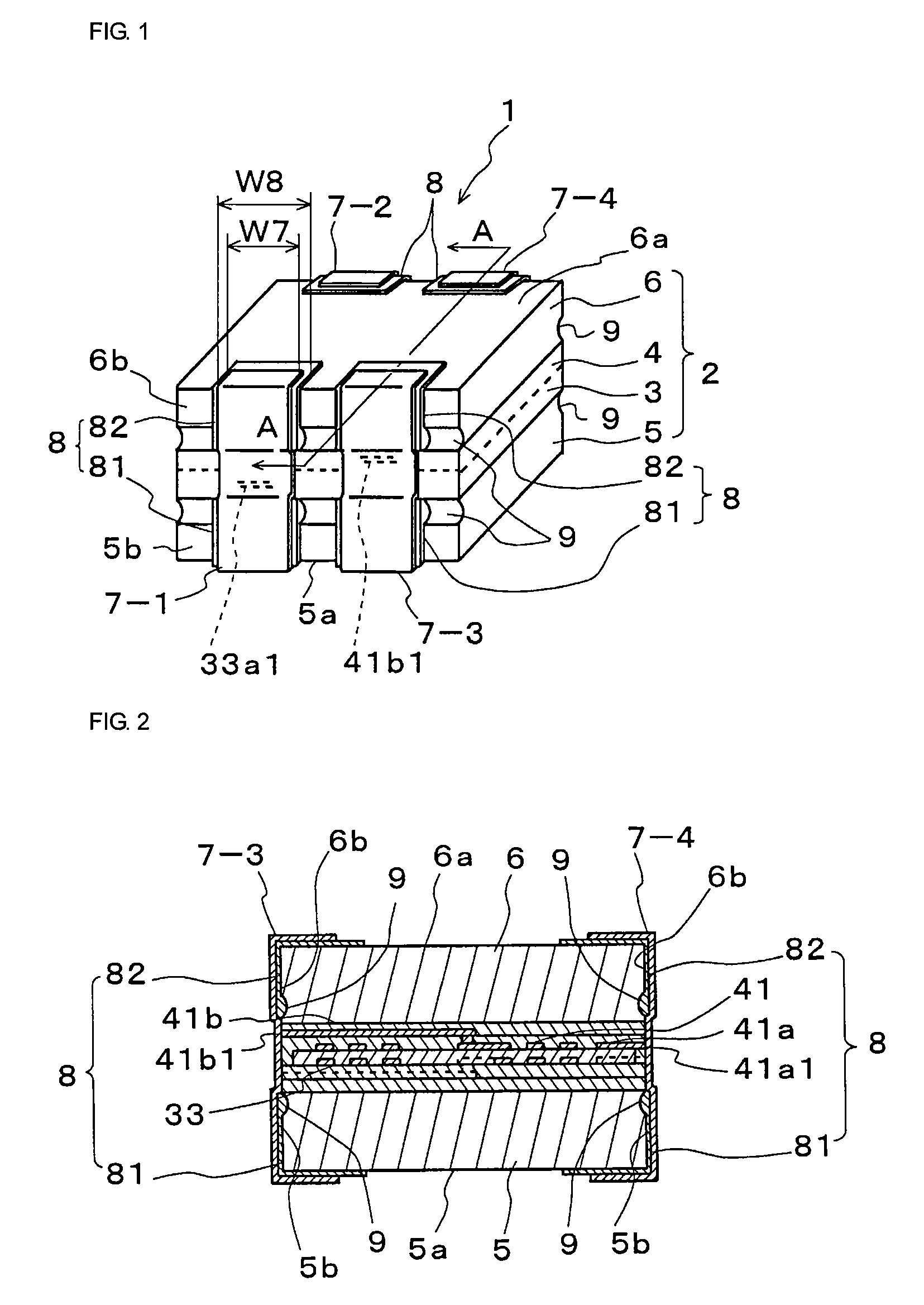
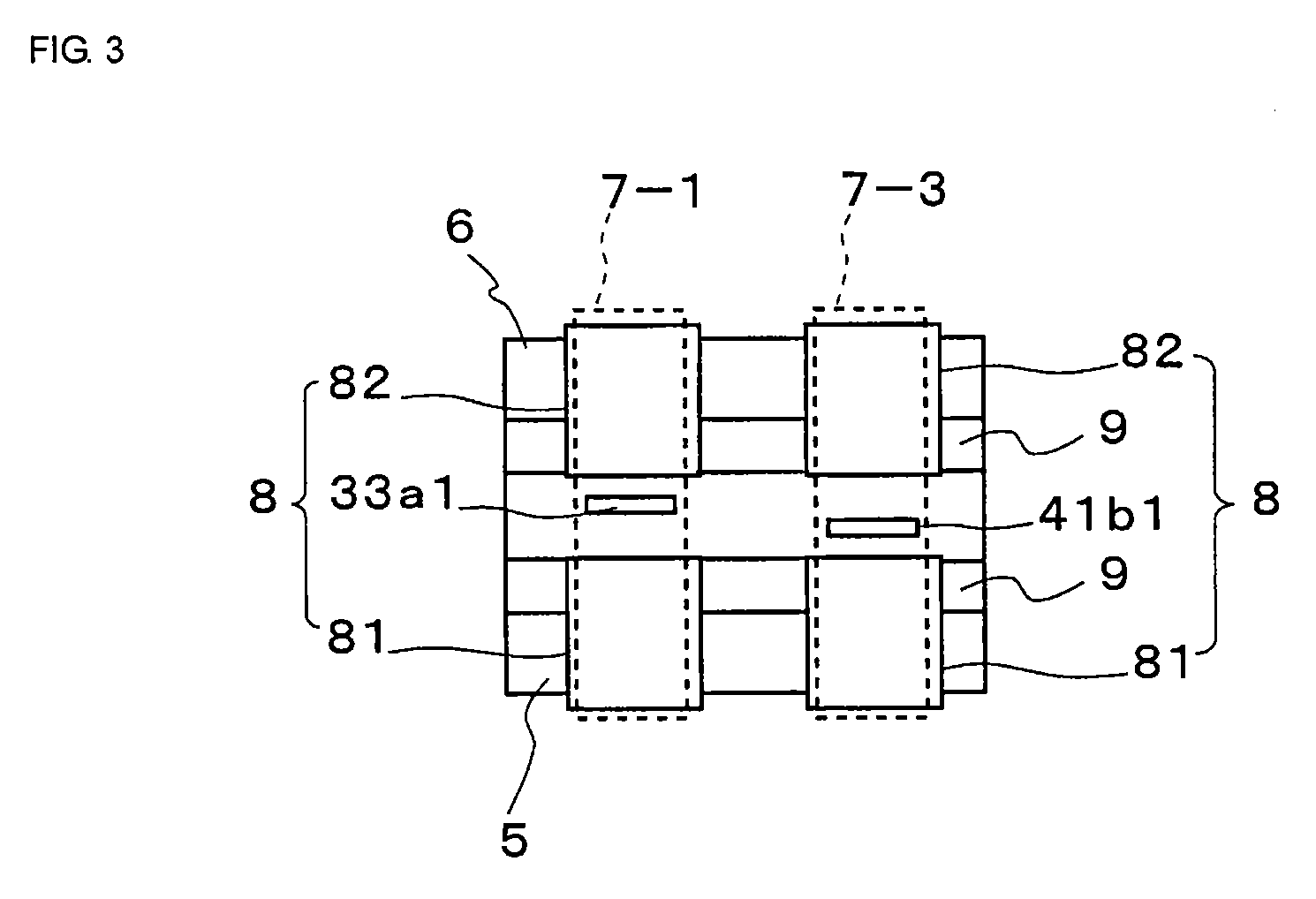
[0047]FIG. 1 is an outside view of an electronic component according to a first embodiment of the present invention, FIG. 2 is a cross-sectional view, as viewed from the directions of arrows A-A in FIG. 1, FIG. 3 is a front view of the electronic component, showing exposed portions of coil patterns, and FIG. 4 is an exploded perspective view of the electronic component.
[0048]An electronic component 1 according to this embodiment is a common-mode choke coil, and includes a chip body 2 and first to fourth outer electrodes 7-1 to 7-4, as shown in FIGS. 1 and 3.
[0049]In the chip body 2, first and second coil blocks 3 and 4 serving as circuit blocks are sandwiched between magnetic substrates 5 and 6 serving as substrate elements from above and below.
[0050]As shown in FIG. 4, the first block 3 includes insulating layers 31 and 32 and a coil pattern 33 that are stacked on the magnetic substrate 5.
[0051]More specifically, the insulating layer 31 is placed on the magnetic substrate 5, and on...
second embodiment
[0090]A second embodiment of the present invention will now be described.
[0091]FIG. 11 is a front view of an electronic component according to a second embodiment of the present invention, and FIG. 12 is a schematic partial sectional view explaining the operation and advantages of the second embodiment.
[0092]The electronic component according to this embodiment is different from the above-described first embodiment in that the characteristic impedance is reduced near the outer electrodes 7-1 to 7-4.
[0093]More specifically, as shown in FIG. 11, a single dielectric layer 8′ that is not split is formed over the adjacent outer electrodes 7-1 and 7-3 (7-2 and 7-4). That is, the single dielectric layer 8′ is provided under the outer electrodes 7-1 and 7-3 (7-2 and 7-4) so as not to cover leading ends 33a1 (33c1) and 41b1 (41a1) of coil patterns 33 and 41, so that the dielectric layer 8′ also lies between the adjacent outer electrodes 7-1 and 7-3 (7-2 and 7-4). The dielectric constant of t...
PUM
| Property | Measurement | Unit |
|---|---|---|
| dielectric constant | aaaaa | aaaaa |
| dielectric constant | aaaaa | aaaaa |
| dielectric constant | aaaaa | aaaaa |
Abstract
Description
Claims
Application Information
 - R&D
- Intellectual Property
- Life Sciences
- Materials
- Tech Scout
- Unparalleled Data Quality
- Higher Quality Content
- 60% Fewer Hallucinations
Browse by: Latest US Patents, China's latest patents, Technical Efficacy Thesaurus, Application Domain, Technology Topic, Popular Technical Reports.
© 2025 PatSnap. All rights reserved.Legal|Privacy policy|Modern Slavery Act Transparency Statement|Sitemap|About US| Contact US: help@patsnap.com


