Liquid Chromatography Apparatus

a liquid chromatography and apparatus technology, applied in the field of multi-column liquid chromatography apparatus, can solve the problems of complex apparatus, large multi-layer microtechnology structure, difficult operation, etc., and achieve the effect of effectively delineating hollow nipples or needles and efficient fraction delivery

Inactive Publication Date: 2008-06-12
VARIAN AUSTRALIA PTY LTD
View PDF16 Cites 38 Cited by
  • Summary
  • Abstract
  • Description
  • Claims
  • Application Information

AI Technical Summary

Benefits of technology

[0053]Preferably the fraction collection sheet is formed by deforming a thin inert plastic sheet through heat and pressure so as to form the rows and columns of indentations or wells. A wide variety of plastic materials may be used, for example 300 micron thick polypropylene sheet. The spacing between the columns of wells can match the spacing of the outlets from the flow cells, which may be the same as the chromatography column spacing of the column plate. The spacing between individual indentations or wells within each column (that is, the spacing between the rows) depends on the desired volume of each well but a spacing between about 3 and 9 mm may be considered typical. By providing effectively a “continuous” strip of fraction collection sheet, an operator of th

Problems solved by technology

Such apparatus is complex and tends to be difficult to operate, moreover it is relatively slow, for example a typical separation and analysis time could take several minutes, which is quite inefficient when there are many samples for analysis.
The multilaye

Method used


Image

  • Liquid Chromatography Apparatus
  • Liquid Chromatography Apparatus
  • Liquid Chromatography Apparatus

Examples


Embodiment Construction

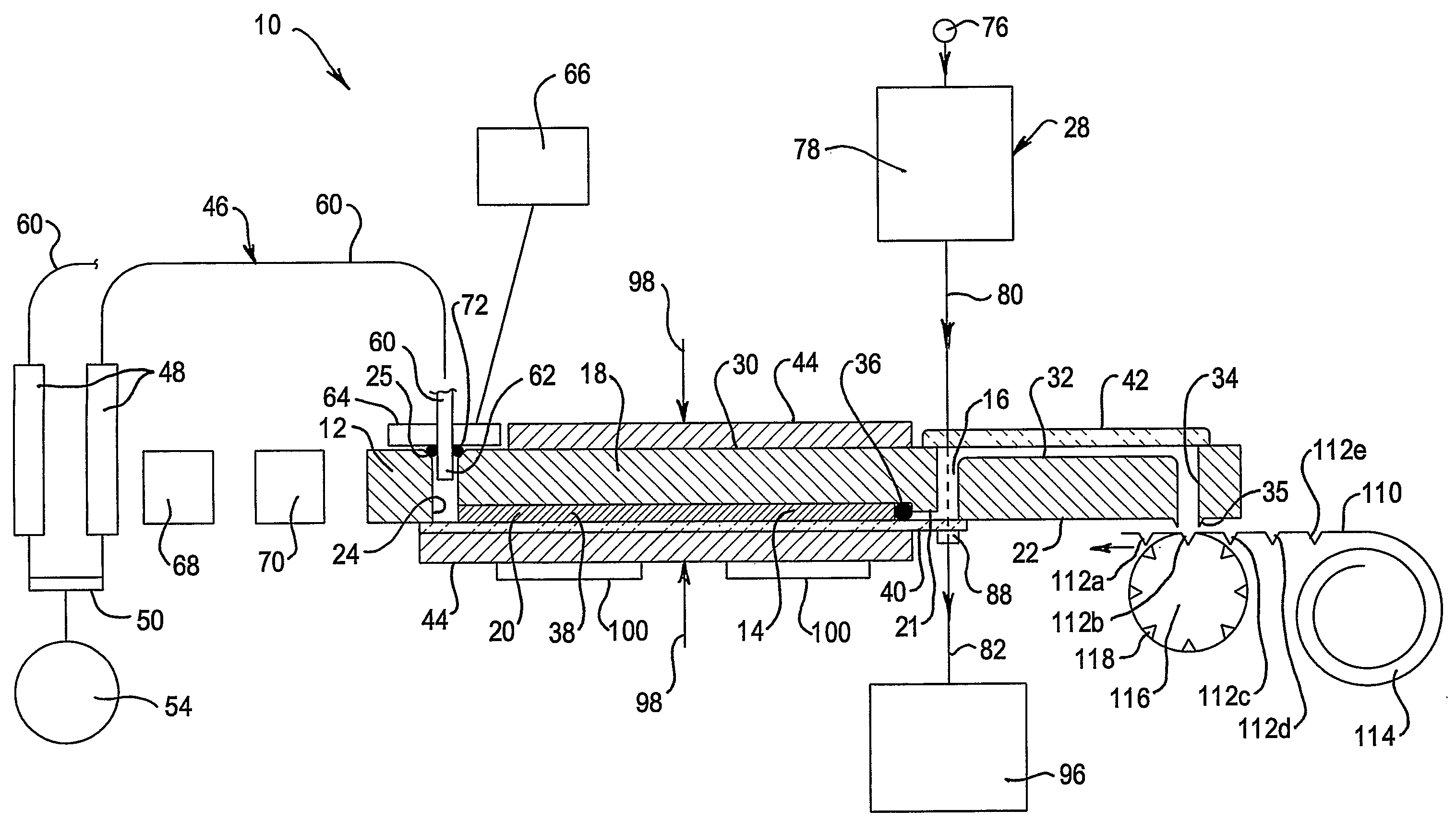
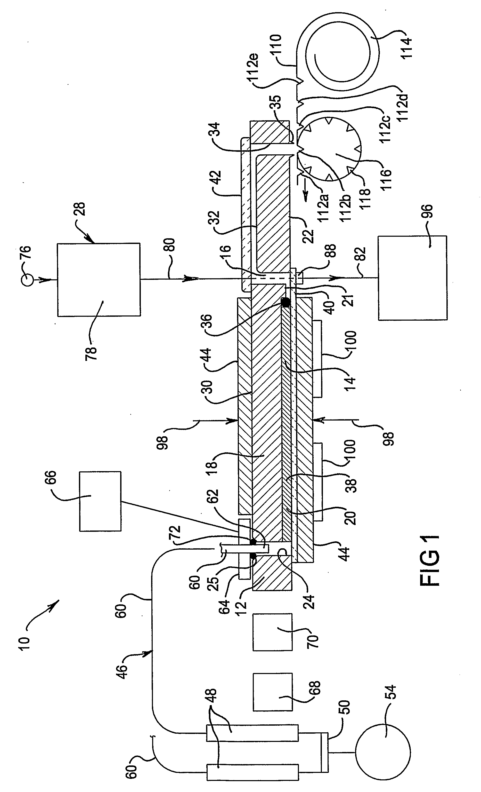
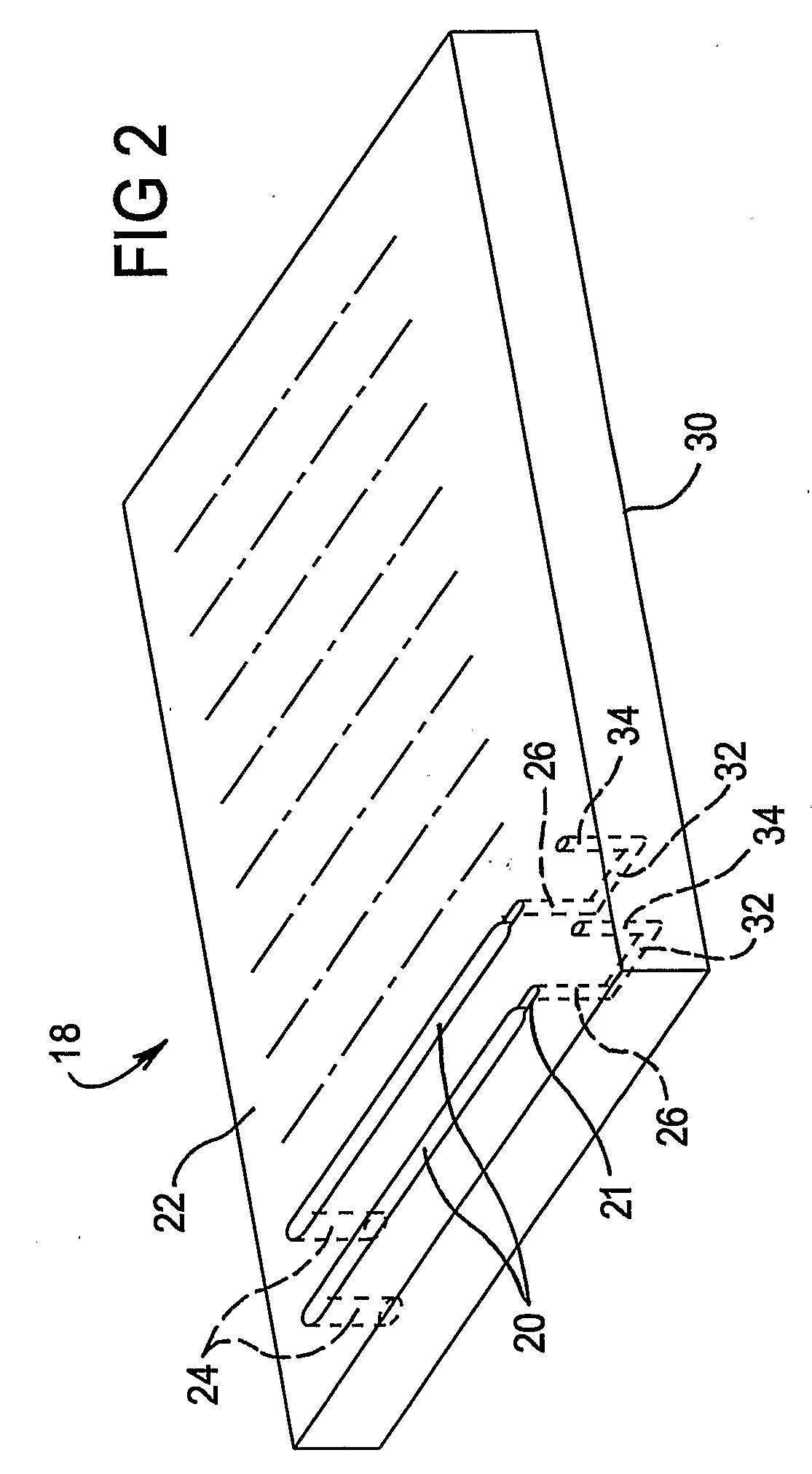
[0071]With reference to FIG. 1, a multi-column liquid chromatography system 10 according to an embodiment of the invention includes a column plate 12 that incorporates a plurality, for example twelve or twenty four, of liquid chromatography columns 14 (only one of which is shown in the FIG. 1 schematic cross-section) for performing a plurality of liquid chromatography separations in parallel. The column plate 12 also includes a flow cell 16 at an outlet of each column 14. The column plate 12 is made from a moulded plate 18 (see FIG. 2), that includes parallel first grooves 20 in a surface 22 thereof which are for forming the chromatography separation columns 14. A smaller cross-sectioned second groove 21 leads from each groove 20 for providing an outlet path from each chromatography column 14. The moulded plate 18 also includes through holes 24, each associated with one end of a respective first groove 20, for providing an inlet for each chromatography column 14. Further through hol...


PUM


Abstract

A multi-column liquid chromatography system (10) for performing a plurality of liquid chromatography separations in parallel is based on a column plate structure (12) having parallel grooves (20) formed in a surface (22) of a plate (18), a cover sheet (40) bonded to the surface (22) to cover the grooves (20) and a stationary phase (38) contained in each covered groove (20). Through holes (24, 26) in the plate (18) define respective inlets (24) for the chromatography columns (14) and flow cells (16) at outlets, with the cover sheet (40) providing an optically transparent end wall for the flow cells (16) and another cover sheet (42) bonded to the opposite surface (30) of the plate (18) providing the other optically transparent end wall for the flow cells (16). Thus merely three parts need be provided for a structure for providing the chromatography columns, that is, a plate having grooves and through holes plus two cover sheets. The chromatography system (10) additionally includes a pumping system (46) comprising a syringe pump (48) for each column (14), an optical system (28) for transmitting analytical radiation through the flow cells (16) and a fraction collection sheet (110) containing wells (112) which is fed past outlets (34-35) from the column plate structure (12).

Description

TECHNICAL FIELD[0001]The present invention relates to liquid chromatography and in particular to multi-column liquid chromatography apparatus for performing a plurality of liquid chromatography separations in parallel. The invention also relates to various components for providing a multi-column liquid chromatography system.BACKGROUND[0002]The discussion herein of the background to the invention and the prior art is included to explain the context of the invention. This is not to be taken as an admission that any of the material referred to was, in Australia, published, known or part of the common general knowledge in the art as at the priority date of the claims.[0003]Liquid chromatography is a physical separation method wherein liquid solvent (that is, “a mobile phase”) carries a sample mixture through a separation medium (that is, “a stationary phase” contained in a column) for the sample to be separated into its different constituents due to each constituent of the sample intera...

Claims


Application Information

Patent Timeline
IPC IPC(8): B01D15/08
CPCG01N21/03G01N30/466G01N2021/0346G01N30/92G01N2030/027G01N30/74
Inventor HAMMER, MICHAEL R.
Owner VARIAN AUSTRALIA PTY LTD
Why Eureka
Try Eureka