[0021]This invention details improvements to applicants' previous U.S.
patent application Ser. No. 11 / 747,899 EXCLUSION DEVICE AND
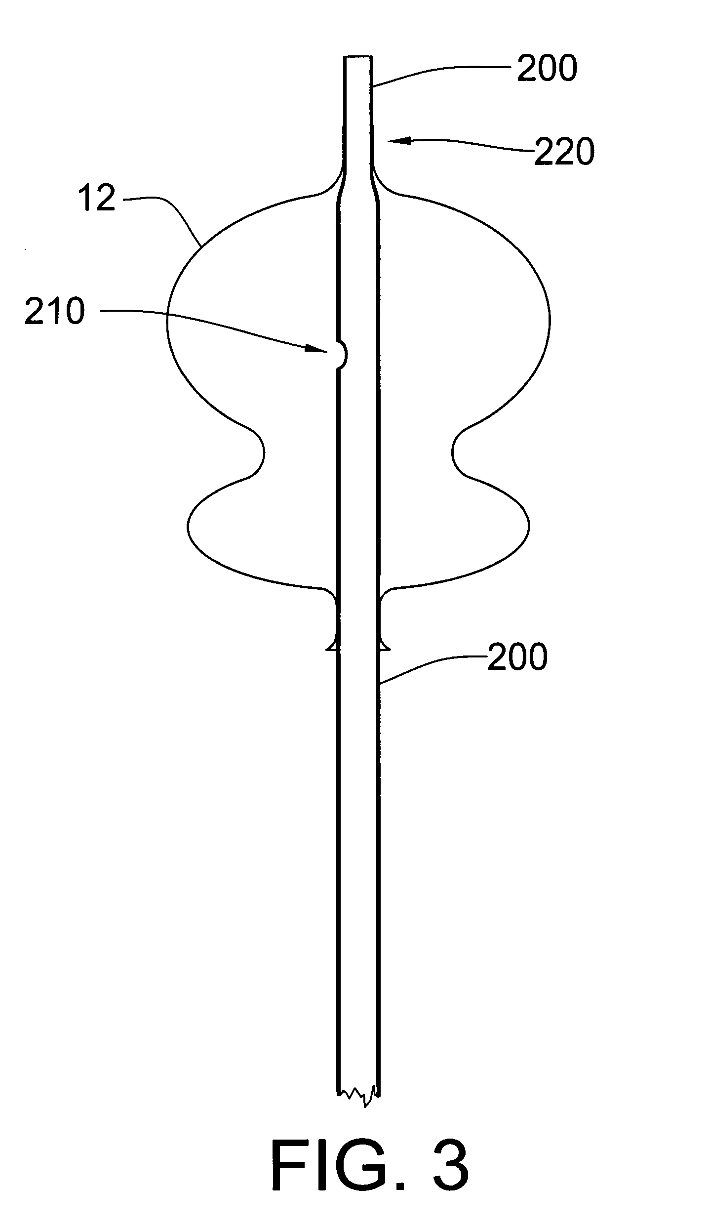
SYSTEM FOR DELIVERY. The current invention details a method to alter the device itself, which enables the herein disclosed delivery and deployment improvements. This invention provides an alternate collapse and disconnect method by adding a second port to the device such that the device can be delivered with a guidewire running through its center. This invention also provides increased stability, deliverability, and deployability, due to its unique two ports, over a guidewire, design. The design facilitates collapse and detachment via the relative movement of two coaxial
catheter tubes. One simple movement accomplishes both tasks without the need for additional hardware or complicated thermal or galvanic systems of detachment. The
delivery system provides a tubular connection between the aneurismal sac and the outside of the body, allowing the aspiration of blood from the sac and the introduction of therapeutic drugs, devices, or compounds into the sealed sac prior to
catheter detachment from the exclusion device. This invention will be referred to herein as the “over-the-wire” exclusion device and endovascular
delivery system. The device, when deployed in a lumen or orifice, reduces the flow of fluid past the device. Undesirable device movement due to
blood flow during delivery and deployment are far better handled with this over-the-wire version of the exclusion device
assembly.
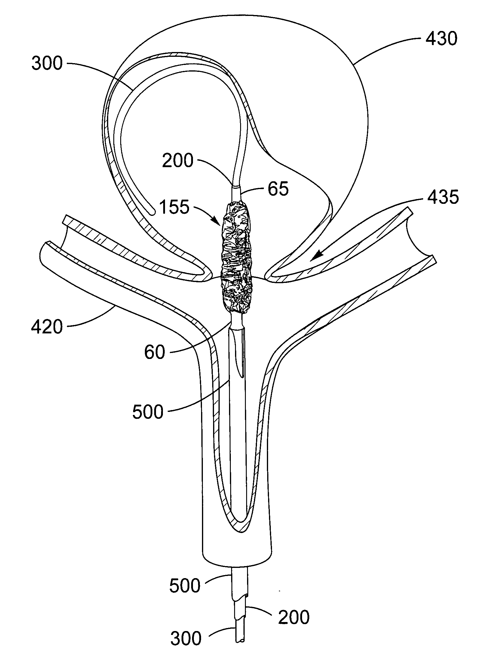
[0022]In an illustrative embodiment, the device is delivered endovascularly to the neck of an aneurysm and deployed to block the neck of the aneurysm, thereby reducing
blood flow into the aneurysm. The deployment leaves the
parent artery fully open and does not block perforator arteries that may exist near the aneurysm. In addition, the present invention treats aneurysms at bifurcations and aneurysms located on the side of an artery.
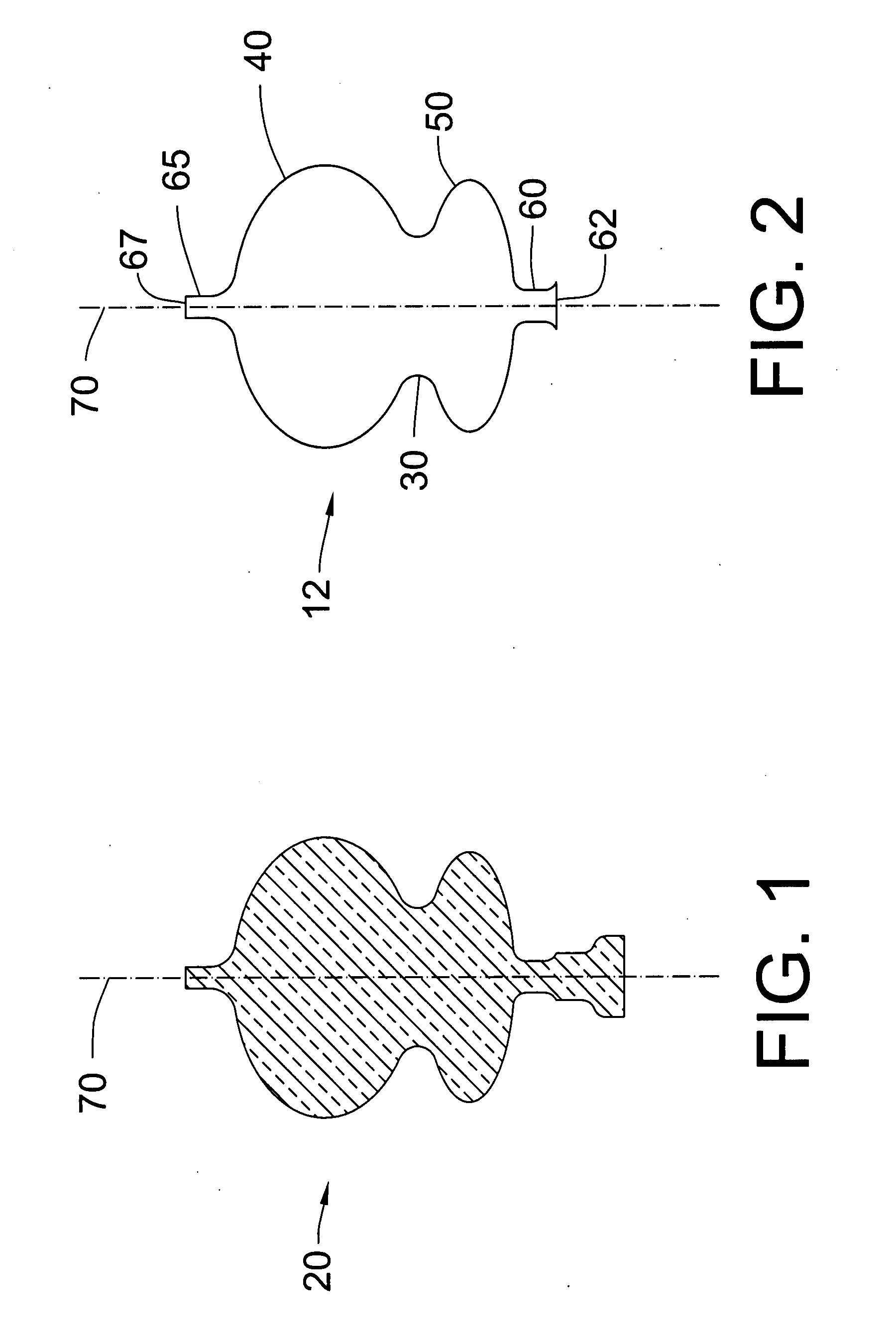
[0023]The exclusion device of the present invention, a thin-walled, ductile shell, transitions between an initial as-manufactured shape, a compacted delivery shape, a pressure expanded shape similar to the as-manufactured shape, a mechanically collapsed shape, and a final
balloon-contoured shape. When deployed at the neck of an aneurysm, the exclusion device reduces
blood circulation into the aneurysm, triggering a
thrombus in the aneurysm that starts the healing process.
[0030]An exclusion device, manufactured and deployed as described by this invention, may be used to treat a patient with an aneurysm which has a significant leak or which has ruptured completely. The over-the-wire design provides greatly increased stability during delivery and deployment. The present invention provides a treatment option for quickly sealing the neck of an aneurysm in a
single step, unlike multiple coil deployments which take much longer. Shorter procedures are always desirable but become crucial when treating
stroke caused by a bleeding or ruptured aneurysms. The simplicity, speed, and consistency with which an over-the-wire exclusion device may be deployed make this invention a unique and useful treatment option. The device, once deployed across the neck of a ruptured or leaking aneurysm, provides an immediate barrier to flowing blood, with no need to wait for
thrombus formation, as is the case with coiling and non-
solid, (e.g. fabric or screen)
aneurysm neck sealing devices. A device for use in these urgent cases, with highly dynamic flowing and pulsing blood, must be very stable, easily directed, and reliably deployable, characteristics provided by only the present invention.

