
Method of making a heat exchanger

Active Publication Date: 2008-06-26
THE BOEING CO
View PDF10 Cites 55 Cited by
  • Summary
  • Abstract
  • Description
  • Claims
  • Application Information

AI Technical Summary

Benefits of technology

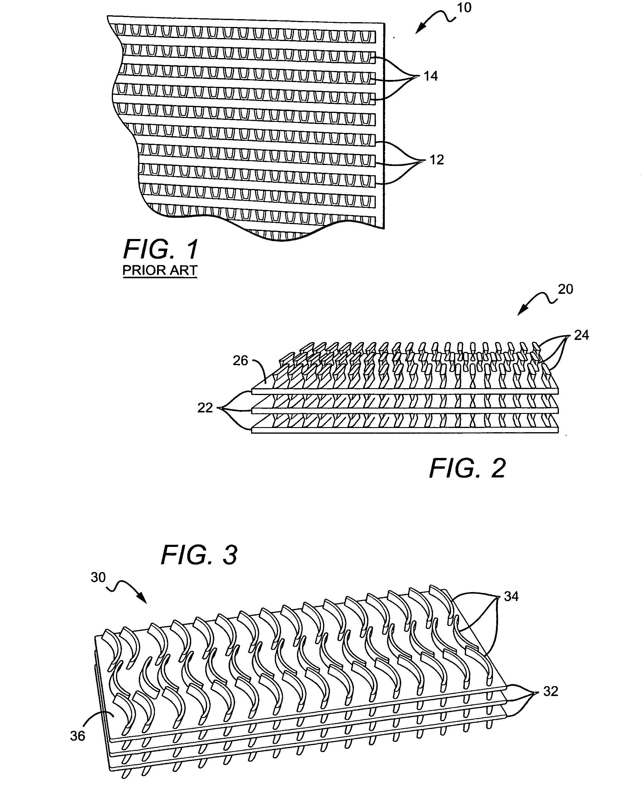
[0005]This need for a method of making a heat exchanger that does not have the problems associated with known methods, as well as a unique, nonobvious, and advantageous method, is satisfied. None of the known methods provides all of the numerous advantages discussed herein. Unlike known methods, an embodiment of the method of making a heat exchanger may provide one or more of the following advantages: reduced manufacturing cost and improved efficiency; applies additive manufacturing techniques to grow heat exchangers and compact heat exchangers; the use of additive manufacturing provides that increased complexity of components does not add to manufacturing costs; the use of an additive process enables the use of more complex geometries in the exchanger assembly when needed; the fabrication process will grow the heat exchanger or compact heat exchanger in one piece, complete with core, exterior, interfacing flanges, fins, and manifolds; eliminates assembly operations and maintenance of tools; and, provides the ability to manufacture complex monolithic structures as an alternative to brazing intense assemblies.

Problems solved by technology

None of the known methods provides all of the numerous advantages discussed herein.

Method used


Image

  • Method of making a heat exchanger
  • Method of making a heat exchanger

Examples


Embodiment Construction

[0012]Embodiments of the invention now will be described more fully hereinafter with reference to the accompanying drawings, in which some, but not all embodiments of the invention are shown. Indeed, several different embodiments may be provided and should not be construed as limited to the embodiments set forth herein. Rather, these embodiments are provided so that this disclosure will be thorough and complete and will fully convey the scope of the invention to those skilled in the art. Like numbers refer to like elements throughout.

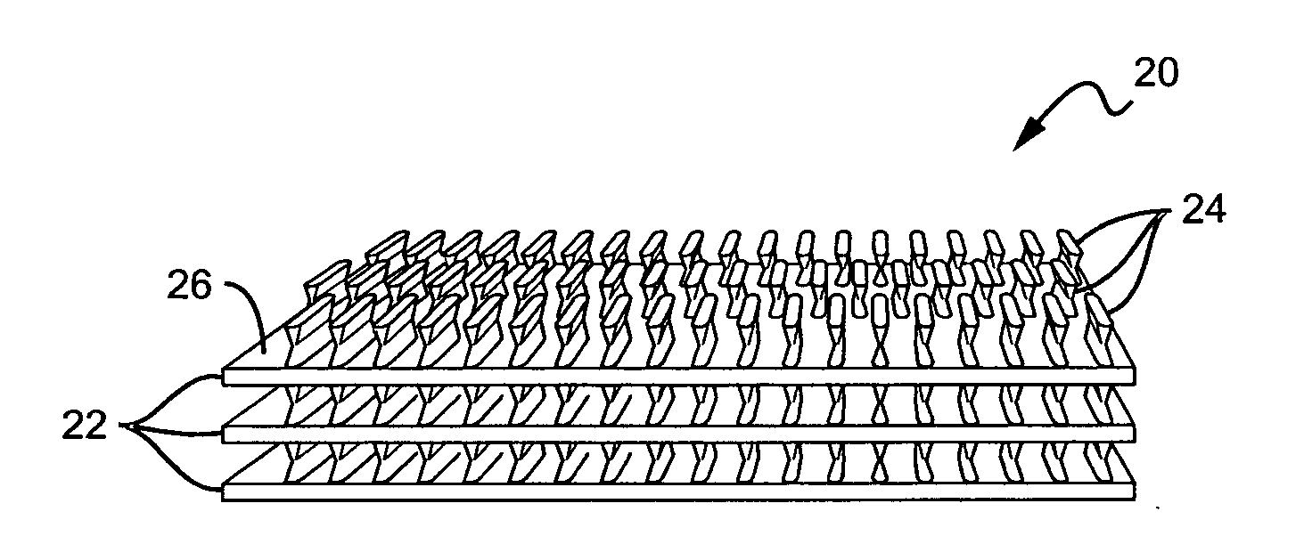
[0013]Referring now to the drawings, FIG. 1 is a front view of a prior art compact heat exchanger 10 formed with a series of stacked plates 12. Each plate 12 has a plurality of rows of fins 14 connected to each plate 12. FIG. 2 is a perspective view of an embodiment of a compact heat exchanger 20 made from an embodiment of the method of the invention. The compact heat exchanger 20 is formed with a series of stacked plates 22. Each plate has a plurality ...


PUM

PropertyMeasurementUnit
Thicknessaaaaaaaaaa
Thicknessaaaaaaaaaa
Surfaceaaaaaaaaaa

Abstract

In one embodiment, a method of making a heat exchanger is provided, comprising the steps of generating a stereolithography file from design data, slicing the stereolithography file into two-dimensional patterns, and depositing at least one layer of a material having a high thermal conductivity onto a top surface of a substrate to form a heat exchanger. Preferably, the heat exchanger does not require assembly of separate pieces to form the heat exchanger. In another embodiment a heat exchanger made by this embodiment of the method is provided wherein the heat exchanger may have a design comprising tapered fins and / or alternating airfoil cross-sections.

Description

BACKGROUND OF THE INVENTION[0001]1) Field of the Invention[0002]A method of making a heat exchanger is provided. More particularly, a method of making a compact heat exchanger by an additive process is provided.[0003]2) Description of Related Art[0004]Known heat exchangers are devices built for efficient heat transfer from one fluid to another, whether the fluids are separated by a solid wall so that they never mix, or the fluids are directly contacted. Heat exchangers are typically used in refrigeration, air conditioning, space heating, electricity generation, and chemical processing. Heat exchangers are of particular use in the aerospace and automobile industries. For efficiency, heat exchangers are designed to maximize the surface area of the wall between the two fluids, while minimizing resistance to fluid flow through the exchanger. The heat exchanger's performance can also be affected by the addition of fins or corrugations in one or both directions, which increase surface are...

Claims


Application Information

Patent Timeline
IPC IPC(8): F28D1/00
CPCB22F3/1055F28F3/048F28F21/081F28F13/06F28F7/02Y02P10/25B22F10/28B22F10/25B22F12/17B29C67/00F28F21/08B22F10/00
Inventor SLAUGHTER, VICTOR BLAKEMORE
Owner THE BOEING CO
Learn More