
Arrangement structure of component parts for fuel cell vehicle

a fuel cell and component technology, applied in the direction of battery/cell propulsion, jet propulsion mounting, electrochemical generators, etc., can solve the problems of difficult to freely arrange the component parts of the vehicle, and easy damage to the component parts, etc., to reduce noise and improve the weight distribution of the vehicle

Inactive Publication Date: 2008-06-26
HYUNDAI MOTOR CO LTD
View PDF9 Cites 25 Cited by
  • Summary
  • Abstract
  • Description
  • Claims
  • Application Information

AI Technical Summary

Benefits of technology

[0016]The present invention has been made in an effort to solve the above problems. One object of the invention is to provide an arrangement structure of component parts for a fuel cell vehicle that efficiently arranges various component parts of a fuel cell system, a hydrogen supply system and an electric driving system, as well as an engine room, an under-floor and a trunk room to make the best use of interior space, improve weight distribution of the vehicle, reduce noise, and provide security against a rear-end collision.
[0017]Another object of the present invention is to provide an arrangement structure of component parts for a fuel cell vehicle that eliminates unnecessary interference between the component parts and prevents the component parts from being damaged when a collision accident occurs.
[0018]Still another object of the present invention is to provide an arrangement structure of component parts for a fuel cell vehicle that reduces the number of manufacturing processes to improve productivity and earn economic profits.

Problems solved by technology

Meanwhile, available spaces for the respective component parts are limited in the vehicle.
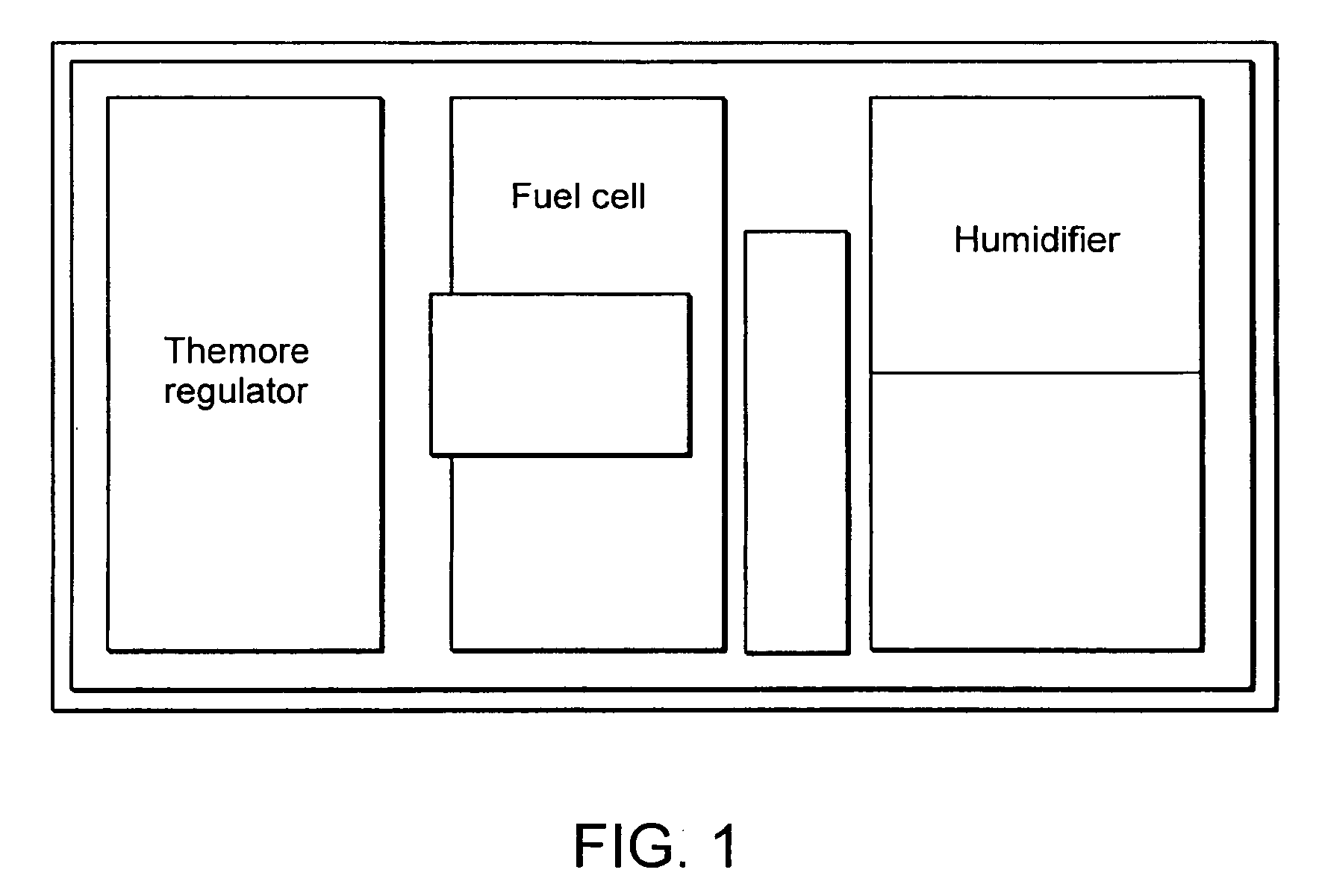
However, since the thermoregulator, fuel cell, humidifier, and hydrogen tank are arranged in a row from the front portion of the vehicle, there are dimensional limitations in the longitudinal arrangement of the vehicle and thereby it is difficult to freely arrange the component parts of the vehicle.
Moreover, the above conventional arrangement structure has a problem that the component parts may be easily damaged when a collision accident occurs since the distances between the component parts are too short.
However, since the process of assembling the respective motor, the fuel cell and the power control unit in the sequential order is complicated, the manufacturing cost is increased due to the increase in the number of assembling processes.

Method used


Image

  • Arrangement structure of component parts for fuel cell vehicle
  • Arrangement structure of component parts for fuel cell vehicle
  • Arrangement structure of component parts for fuel cell vehicle

Examples


Embodiment Construction

[0040]Reference will now be made in detail to the preferred embodiment of the present invention, examples of which are illustrated in the drawings attached hereinafter, wherein like reference numerals refer to like elements throughout. The embodiments are described below so as to explain the present invention by referring to the figures.

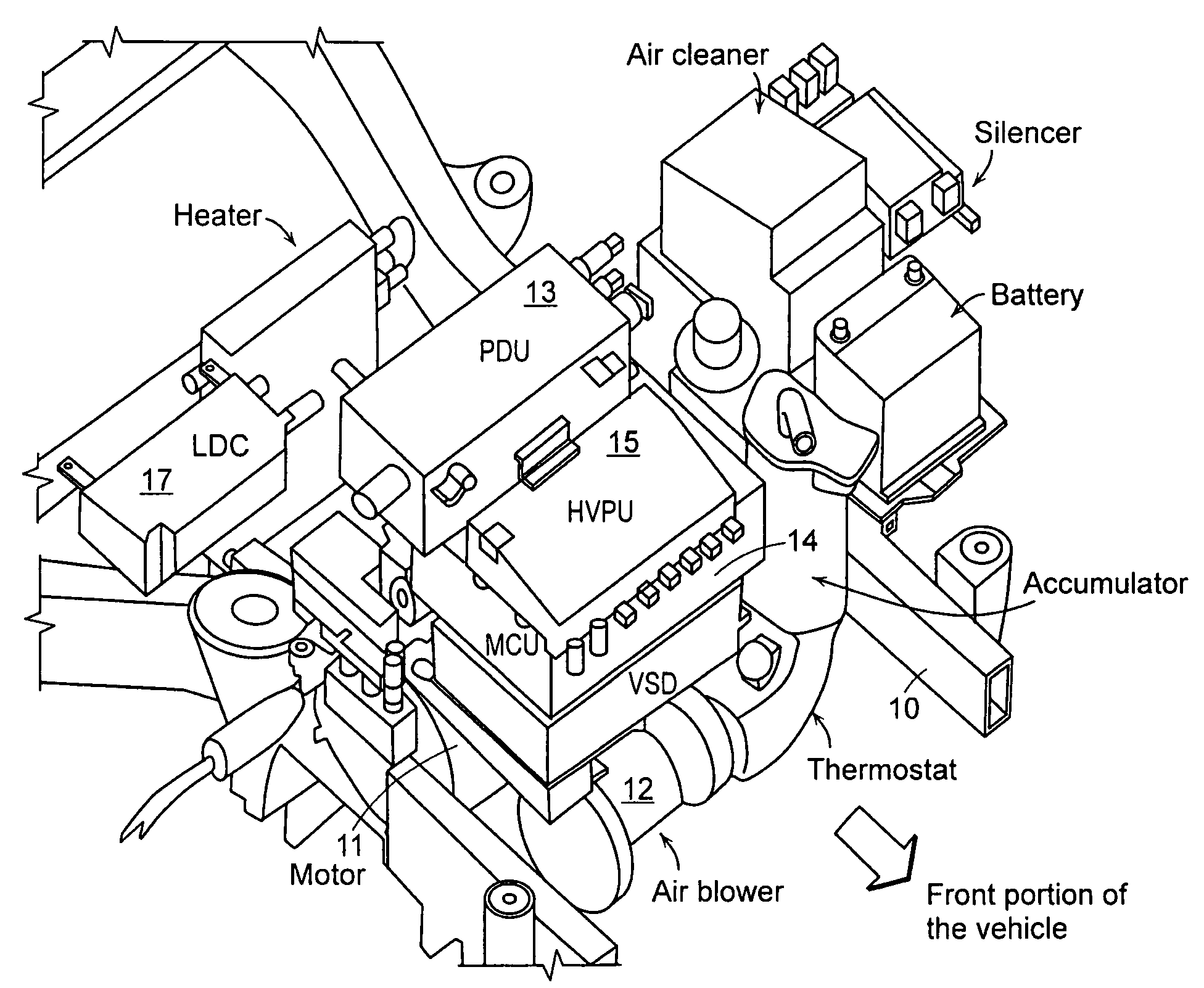
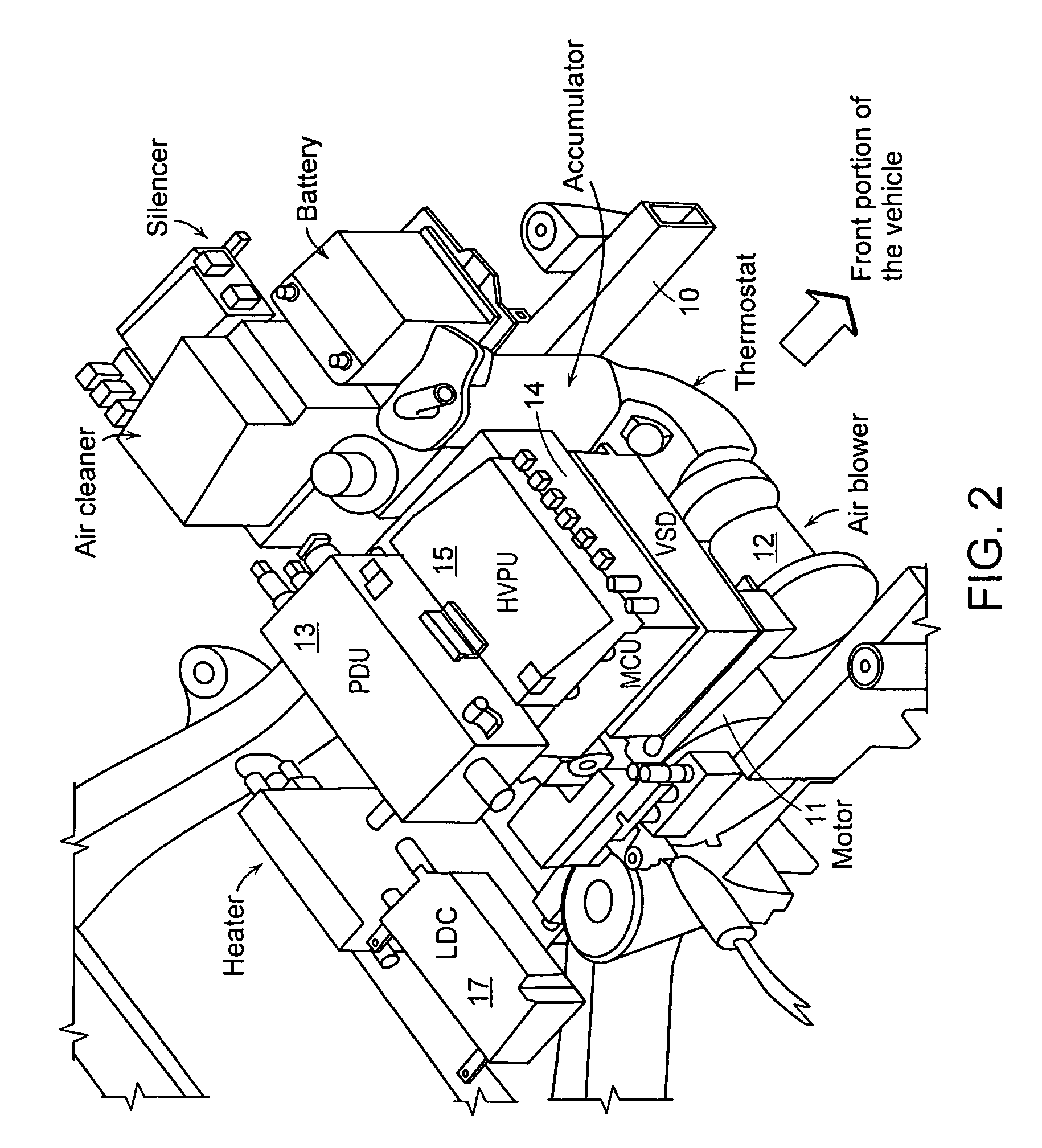
[0041]With reference to FIGS. 2 and 3, in a fuel cell vehicle, a motor 11, an air blower 12, and various component parts of an electrical system and a fuel cell system such as a power distribution unit (PDU) 13, a motor control unit (MCU) 14, a high-voltage power distribution (HVPD) 15, an electro-hydraulic power steering (EHPS) system, a low-voltage DC / DC converter (LDC) 17, and the like are mounted in an engine room.

[0042]In the present invention, the motor 11 and the air blower 12 are mounted on the upper portion of a frame 11 using separate mounting members.

[0043]Although the MCU 14 and the like may be mounted in an appropriate position of the fr...


PUM


Abstract

The present invention provides an arrangement structure of component parts for a fuel cell vehicle that efficiently arranges various component parts of a fuel cell system, a hydrogen supply system and an electric driving system to make the best use of interior space, improve weight distribution of the vehicle, reduce noise, and provide security against a rear-end collision.The arrangement structure of the present invention includes an engine room, in which a motor 11 and an air blower 12 are mounted on an upper portion of a frame 10, and component parts of an electrical system and a fuel cell system are arranged on an upper portion of the motor 11; an under-floor 20, on which a humidifier 21, a stack 22, a fuel processing system (FPS) box 23, and a hydrogen tank 40 are mounted; seats 29, beneath which electronic parts are arranged on the under-floor 20; and a trunk room, in which a super-capacitor and an initial charging device are mounted.

Description

CROSS-REFERENCE TO RELATED APPLICATION[0001]This application claims the benefit under 35 U.S.C. §119(a) on Korean Patent Application No. 10-2006-0127953 filed on Dec. 14, 2006, the entire contents of which are incorporated herein by reference.BACKGROUND[0002](a) Technical Field[0003]The present invention relates to an arrangement structure of component parts for a fuel cell vehicle.[0004](b) Background Art[0005]A fuel cell vehicle is equipped with a fuel cell generation system that generates electric power for driving a motor to operate a vehicle.[0006]In detail, a fuel processing system (FPS) box for supplying hydrogen to a fuel cell, a high-pressure hydrogen tank and the like are mounted in a fuel supply system or hydrogen supply system. A control unit including a motor and a motor controller, a secondary cell such as a battery or a super-capacitor, and the like are arranged in appropriate positions of the electric driving system.[0007]Meanwhile, available spaces for the respectiv...

Claims


Application Information

Patent Timeline
IPC IPC(8): B60K6/32
CPCB60K1/04B60K2015/0638H01M8/04126H01M8/04216Y02T90/34H01M16/003H01M2250/20Y02T90/32H01M8/04858Y02T90/40Y02E60/50Y02T10/70Y02T10/7072Y02T90/14B60L50/71B60L15/20B60L53/20B60K15/07B60K2001/0438B60K2015/03315
Inventor YANG, DONG SOOLYOO, SENG JONGKIM, HWAN IK
Owner HYUNDAI MOTOR CO LTD
Learn More